Input of the initial data of the project is carried out with the help of Initial data panel, which contains the following tabs when creating a new operation: Operation, Geometry, Workpiece parameters, Tool parameters, Stop conditions, Boundary conditions, Blows, Simulation parameters:
|
|
Setting of the initial data for simulation. Geometry tab is active |
|

The initial data setup is performed in the following order:
In the Operation tab, the operation name, Operation type, Problem type and other parameters are specified:
The Operation type block specifies which process will be simulated. When simulating the operation type General forming the program by default simulates the visco-plastic deformation of the material taking into account thermal processes: heat transfer of the workpiece with the tool and the environment, thermal conductivity, heat generation as a result of deformation and friction. Thermal processes listed above will not be taken into account in the simulation if the With thermal process check box is deactivated. If the With elastic-plastic deformation check box is activated, the simulation will additionally take into account the elastic properties specified in the deformed material model. Operation type Cooling/Heating involves the simulation of the workpiece cooling or heating as a result of interaction with the environment or tool. If the With elastic-plastic deformation check box is activated, the simulation will also take into account the elastic-plastic properties specified in the deformed material model during cooling or heating. Types of operation Cyclic tool heating, Ring rolling, Wheel rolling, Longitudinal rolling, Cross rolling, Reverse rolling, Extrusion, Profile cooling, Electric upsetting, Sheet-bulk forming - these are special modules that can be used if the appropriate license options are available. In the Problem type tab one of the following types can be selected: 3D, 2D axisymmetric, 2D plane strain. In the Template block it is possiblle to load the initial data for simulation from Operation templates Database. More details are provided in the Operation section. |

The Geometry tab is needed for loading of the initial geometry for simulation or the creation of a parameterized geometry, the setting of symmetry planes and axes, as well as the completion or mirror reflection of objects relative to the symmetry relative to plane . Here you can add, delete, replace or copy geometrical objects, as well as change their properties:
The original geometry is imported by the command Load from file. Geometry for 2D simulations is loaded from *.dxf, *.crs, files. Geometry for 3D simulation - from *.qshape, *.shl or *.step files:
It is also possible to importfinite element mesh with calculated fields from the files with the *.ntl, *.pda, *.unv, *.nas, *.nastran extensions More details are provided in the sections Workpiece parameters and Advanced import options. |


In the Workpiece parameters tab material, initial temperature and other workpiece parameters are indicated:
The Workpiece material is assigned from Database of deformed materials. If the workpiece is transferred from a previous operation, then the default material, temperature , and accumulated general strain are inherited. If necessary, you can disable inheritance and introduce new value. Entering a value in a field Accumulated effective straingg means setting a uniform initial value of plastic strain over the entire volume of the workpieces. When simulating the powder material forming process, it is necessary to specify the relative Density of the material, and when simulating the microstructure, the initial grain size, when simulating phase transformation , it is necessary to set the initial phase and other parameters. If several workpieces are specified in the simulation , it is necessary to assign friction between the workpieces. Friction between workpieces it is also set when it is required to simulate self-contact - friction between the contact surfaces of the same workpiece (in this case, it is necessary to prohibit remeshing the workpieces mesh in the simulation process). Volume change coefficient is used to directly proportionally volume change of the workpieces at the begging of the operation simulation. Gravity positioning (-OZ) is used to automatically place the workpieces in the tool under the action of gravity in the -OZ direction at the beggining of the simulation of the operation. More details are provided in the section Workpiece parameters. |

In the Tool parameters tab tools drives, lubricant between the workpiece and tools, material, initial temperature and other tools parameters are indicated:
Drives are assigned from the Equipment Database. hammer, mechanical, hydraulic, screw press, load holder, as well as a universal drive that allows you to set the translational and rotation movement of the tool are available in the equipment database . All stationary tools are set to the fixed drive type. Lubricant is assigned from the Lubricants Database. In the lubricants model, the parameters of friction and heat transfer between the workpiece and tools are set. Material Tool material is assigned from the Tools materials database. The tool material model contains mechanical and thermophysical properties. It is possible to activate a coupled deformation task:
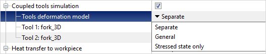
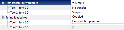
If the parameter Coupled tools simulation is deactivated, the workpieces is general forming with an absolutely rigid tool. If you enable the feature Coupled tools simulation, the deformation of the workpieces will be carried out by an elastic-plastic tool, and the shape of the contact between the tool and the workpiece will change taking into account the deformation of the tool. There are three coupled deformation models by to choose from: Simplified Separate model, in which the deformation of the tool is calculated at each simulation step , and the geometry of the workpieces is corrected in accordance with this deformation, General model, in which the workpiece and tool are deformed as a single system and Stress state only, when the tool simulation is performed at each simulation step , but the nodes of the finite element tool mesh are not displaced, and the tool geometry does not change. When simulating Coupled deformation it is necessary to set tools fixing in the Boundary conditions tab. The following variants for heat exchange between the tool and the workpiece are available in the program: No transfer, Simple, Coupled, Constant temperature:
By the default Simple heat transfer is specified. In this case, the coupled thermal task with the tool is solved, but the tool temperature is calculated only on the surface in contact with the workpiece . At Coupled heat transfer , the tool temperature is calculated in the entire volume. If Constant temperature is specified, then the tool temperature does not change during the simulation . No transfer Heat exchange between tool and workpiece means that on the surface of the workpieces with the tool , heat exchange of the workpieces is carried out not with the tool, but with the environment, and the tool temperature, as in the previous case, does not change. Additionally in the Tool parameters tab you can specify the method of bringing the tools into contact with the workpiece before running the simulation, the friction between the tools, set the spring loaded tool, the spring between two tools , and the parameters of the springs. Tool by tool movement allows you to take into account the interaction of two tools, the drives of which must meet certain conditions. More details are provided in the Tool parameterssection. |

In the Stop conditions tab you must specify one or more conditions to stop the solver. The Simulation will stop when at least one of them is reached. The required condition must be selected in the Add condition window:
The following stop conditions are available: Distance - sets the distance between the specified tools. Time - process time is set. Tool stroke - sets the displacement of the selected tool. Axis 1 (Axis 2) - tool rotation - sets the rotation angle of the tool around the given Axis 1 or Axis 2. Final position - simulation stops when the tool reaches the position user defined during positioning. Maximum load - the simulation stops when the specified load on the specified tool is reached. Field value - the simulation stops when the specified conditions for the calculated fields of the deformable workpieces are reached: Coordinate, Velocity, Temperature, Plastic Strain, Strain rate, Effective stress. Maximal calculation time - the simulation stops when the duration of the simulation exceeds a certain value. It can be useful when simulation several projects sequentially in the batch mode as a safety lock from hangs. More details are provided in the section ***Stop conditions. |

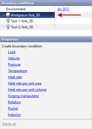
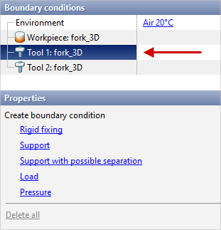
In the Boundaryconditionstab advanced simulation condition can be set: environment parameters , boundary conditions for tools and workpieces:
Environment - this is the environment with which workpieces and tools interact. Properties of the Environment stored in ***DatabasesurroundingWednesdays. The following parameters are indicated in the environment fit by : environment temperature, emissivity , heat transfer coefficient , also for simulation diffusion processes - concentration and mass transfer coefficient. By the default Air 20˚C is specified as the Environment. It is possible to set additional local domains of the environment. With the help of boundary conditions, local velocity, pressure, heat rate and other advanced condition for the workpieces are set. Boundary conditions for tools must be assigned in the case when it is required to tool simulation in the Postprocessor mode or carried out coupled tool deformation simulation.
More details are provided in the Boundary conditions section. |

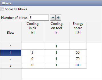
In theBlows tab the number of blows in the operation, the cooling time in the environment and in the tool, and other parameters are specified:
The Energy share parameter is used only for hammer and screw press forging and indicates how much of the equipment's energy is spent per blow. The figure below shows an example of setting the parameters of blows during hammer forging: three blow are set, the transport time from the furnace is 3 seconds, the cooling time of the workpieces in the dies between blows is 1 second, each blow consumes, respectively, 50%, 70%, 100% of the hammer energy :
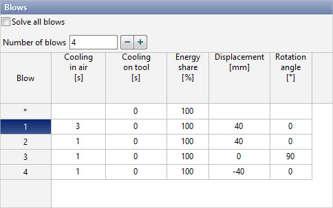
If the workpiece axis is specified, then in the table you can set the displacement and rotation angle of the workpiece relative to the specified axes before each blow. This possibility is used, for example, when simulation free open die forging operation :
More details are provided in the section Blows. |

In the Simulation parameters tab the integration method, step size, mesh parameters, and other simulation parameters are specified. The Simulation parameters are divided into three groups: General, Workpiece mesh, Tool mesh, Workpiece fields:
More details are provided in the section ***Simulation parameters. |

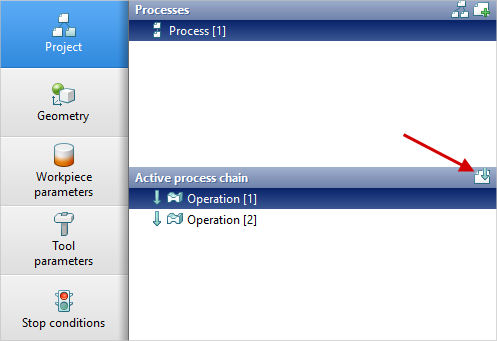
After setting all the initial data of the operation and clicking the OK button in the upper part of the Source Data Panel, the Project tab will appear, which contains all created Operations, Operations chains and Processes. One or more consecutive Operations creates the Operations chain. One or more Operations chains creates the Process. To add the next operation to the chain, select the last operation of the chain in the Active process chain window and in the Properties window click Add operation to process chain:
To create a copy of a Process you need to right-click on the corresponding process and select Create copy of process. To create a copy of an operation, right-click on the corresponding operation and select Create copy of operation. The program will offer to copy all continuations of the selected operation, if there are any:
Clicking the Project structure button opens a window with all created processes and operations chains. In this window, you can activate, create, copy, delete or rename operations and processes, insert or delete intermediate operations, and activate the desired chain of operations.
For more information, see the Project section. |


See also: