In QForm UK two type available 2D problems - plane and axisymmetric.
A typical example plane strain can be the strain in the cross cut plane during the forging of long (elongated) forgings, for example, blades or beams. With a significant length of the forging, there is practically no transfer flow of metal in the longitudinal direction, and all strain occurs in the transverse direction. In this case, it is possible to consider the shape change only of the cross sections of the forging.
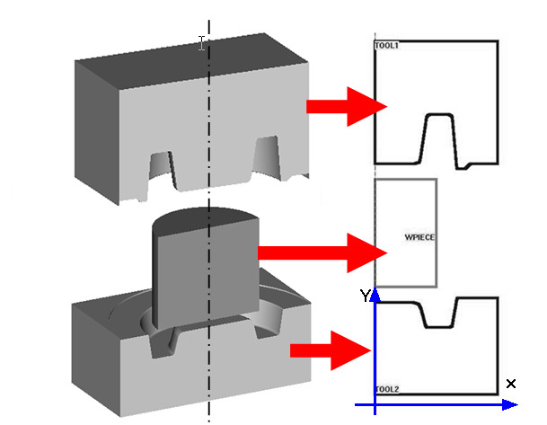
When forging round forgings, the metal spreads evenly in all directions from the axes of symmetry. This flow of metal is called axisymmetric. In this case, the metal flow plane is the meridional cross cut plane of the forging passing through the axis of symmetry. The figure below shows a sketch of an axisymmetric forging, and describes the sequence of preparing 2D contours of tools and a workpieces for simulation:
|
|
|
Sketch of axisymmetric forging and sequence |
|
Cross cut plane of workpieces with two tools (left) |
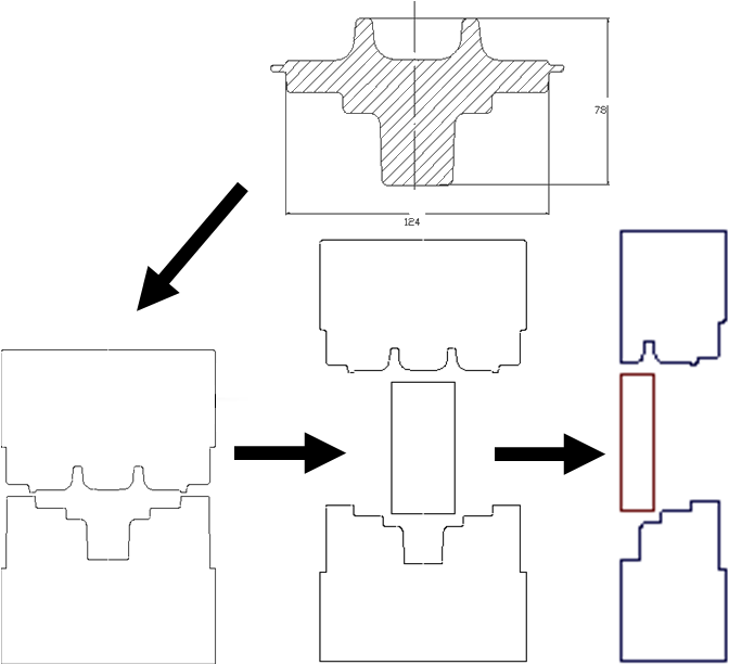
The main requirements for 2D geometry are: the contours of all objects must be closed, there must not be lines overlapping each other if they belong to the same object. When preparing geometry for simulation an axisymmetric task, the contours of tools and workpieces must be located in the plane X0Y, and the axis of symmetry must coincide with the vertical axis 0Y.
Loading 2D contours for simulation in QForm UK possible in two ways:
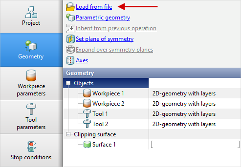
1. Directly from file with *.dxf (ASCII) prepared in any CAD system.
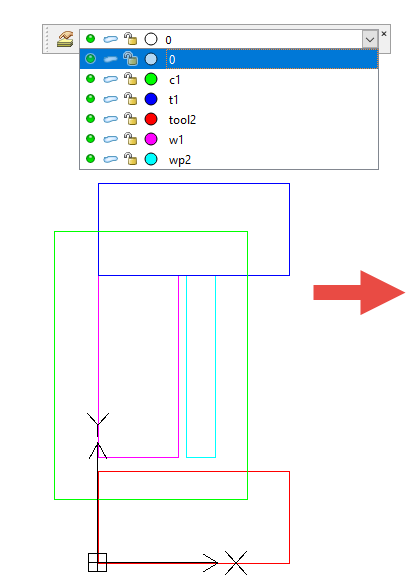
In this case, it is recommended in the CAD system used to immediately designate objects help layer names, then after loading the geometry into QForm UK additionally, you do not have to specify the purpose of the objects and their serial numbers.
Layer naming variants in the CAD system:
•Workpiece [number]: w[number],or wp[number],orwpiece[number],orworkpiece[number]
•Tool [number]: t[number] or tool[number]
•Clipping surface [number]: c[number], or cont[number],or contour[number],or contour[number]
|
|
|
Geometry prepared in the DraftSight CAD system . |
|
Loading geometry into QForm from dxf file |
2. From file with *.crsprepared in the editor QDraft.
Built in QForm UK graphics editor QDraft designed for preparing 2D contours of tools and workpieces. In QDraft the following formats are used:
•*.dxf - Drawing eXchange Format
•*.igs (IGES) – an international standard for the exchange of graphic info for CAD systems
•*.drf (QDraft file format) - own internal format of the applications QDraft
•*.crs – Output format for simulation in QForm UK