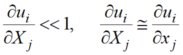
While metal forming the material points of a workpiece acquire significantly displacements. If the distance between the points remains unchanged, then the workpiece moves as a rigid body. If the distance between the points changes, then the strain occurs.
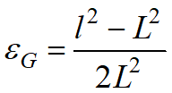
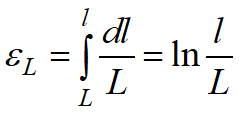
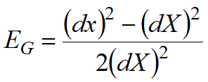
Different quantitative measures of strain are used. In the simplest case of a rod uniaxial tension from initial length L to its finite length l these measures are as follows:
If the strains are small (Δl≈ L), then the above strain measures coincide. These are distinguished the elastic strain εe (superscript e from the English word "elastic") that disappear after external load removal, and the plastic strain εp(superscript p from the English word "plastic") that remain in a workpiece after deforming is complete. |
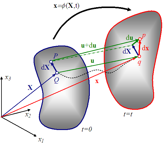
The figure below illustrates the general case of the deformed body movement. The initial position (at t=0) of an arbitrary material point Q is specified with the coordinates
in the initial coordinate system.
At the present moment of time t the point is in the position q that is characterized with the following coordinates
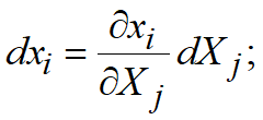
The relationship between the coordinates of the point in its initial position and its current position can be written as:
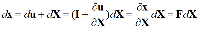
For fixed initial coordinates X this equation describes the trajectory of single point motion (its initial coordinates are fixed). The trajectory is shown with the dashed line. For a fixed moment of time t the equation describes the body configuration (the position of all its points). The displacement vector is equal to the difference between vectors defining the initial and finite position of points
then
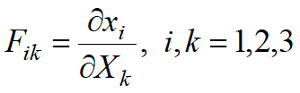
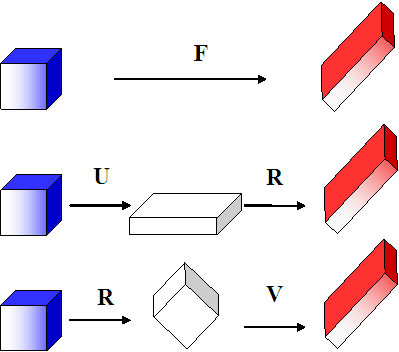
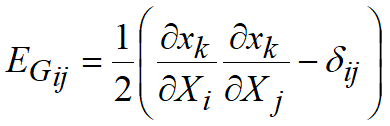
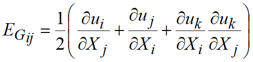
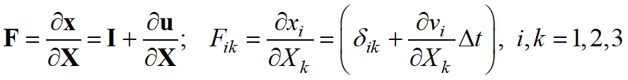
Here I={I} is a unit matrix, F=[F] is a deformation gradient tensor (matrix). Deformation gradient characterizes the transformation of a small volume defined near the material point from the body initial (previous) position to its current position. Generally a change of volume and shape of an elementary unit occurs during this transformation. A deformed body motion may be represented as a sum of its displacement and rotation as a rigid body and its deformation. With the exception of a rigid body motion, the sequence of transformations during shape deformation can be carried out in two ways: first the deformation, and then the rotation, and vice versa.
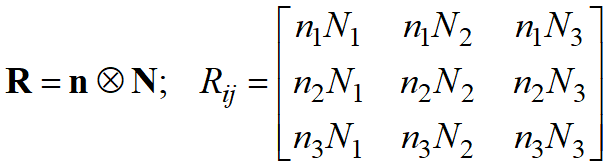
On the basis of theorem on polar decomposition the deformation gradient can be mathematically represented as a product of two matrices:
where R=[R] is the proper orthogonal tensor, or a rotation (matrix of rotation direction cosines, RTR=I), U - left stretch tensor, V - right stretch tensor. Thus, the following sequences of transformations are possible: Deformation, rotation:
Rotation, deformation:
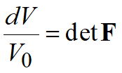
Change of volume
Here V, V0 - current and initial volume, det() is matrix determinant. |
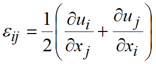
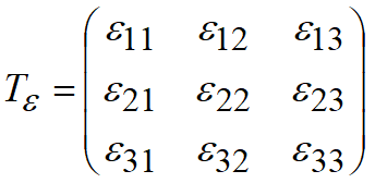
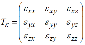
Term strain is used to define the difference between the displacement of small intervals acquired as the result of loading and their displacement as a rigid body.
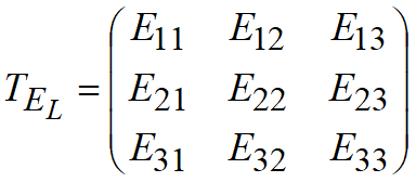
|
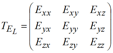

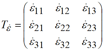
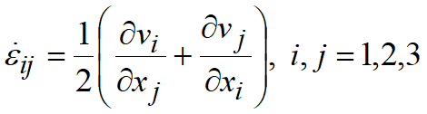
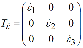
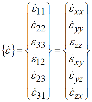
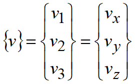
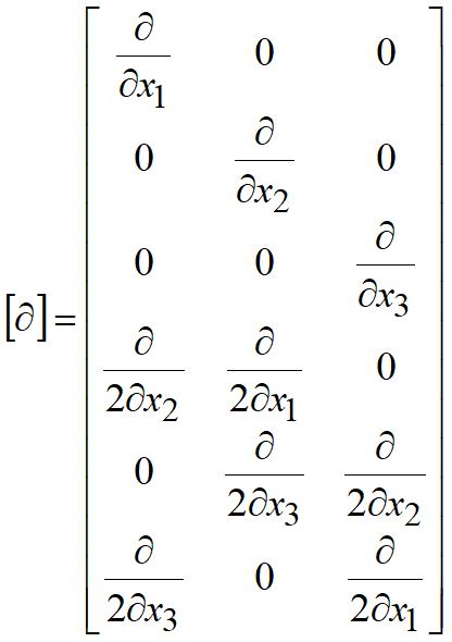
Motion of a continuous medium can be defined with the velocity field of its material points. Let the point of a medium move with a velocity v, when absolute value is determined with the projections on the coordinate axes v1, v2, v3, any of which depends on the coordinates and time. Strain rate tensor is the tensor
here
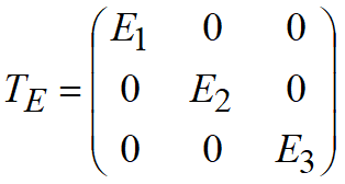
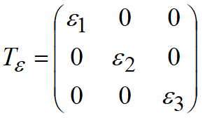
Diagonal components of the strain rate tensor represent the elongation rates of linear elements parallel to corresponding coordinate axes. Shear components are the rates of distortion of initially right angles located in coordinate planes, i.e. the rates of shear strain. Strain rate tensor in the principal coordinate system has a form:
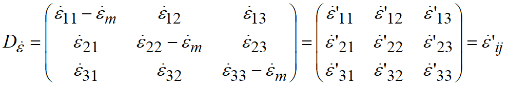
Average strain rate is:
The rate of body volume change is proportional to average strain rate
A tensor derived from the strain rate tensor by subtraction of average strain rate from diagonal components is called the deviatoric strain-rate tensor
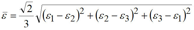
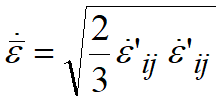
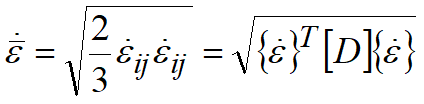
A complex characteristic of the strain rate is the strain rate intensity (effective, equivalent strain rate):
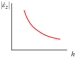
It is important to distinguish between the strain rate and the deformation rate. The first determines the rates of nominal elongations and shears, and has the dimension 1/s. The second is the velocity of material points, it usually means the tool velocity. Deformation rate dimensionality in the international system is m/s. For example, at cylindrical specimen frictionless compression at constant velocity of the deforming tool (deformation velocity) v=const, the strain rate would constantly increase due to the absolute value in proportion to reduction of workpiece height h
The velocity of material points displacement is linearly dependent on z axis
Strain rate
Thus, for the same deformation rate, the less the linear dimensions of the deformed body in the considered direction are, the greater the strain rate due to absolute value will be.
|


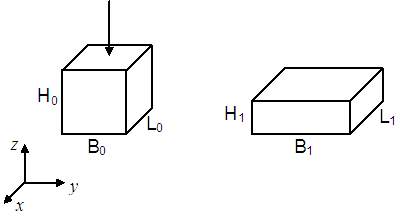
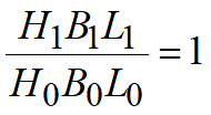
Let the parallelepiped with the initial height H0, width B0 and length L0 be compressed without friction. For this type of deformation its faces will remain flat, and the dimensions of its edges after deformation will reach the values H1, B1, L1, respectively.
Parallelepiped volume in its initial and finite state:
The experiments demonstrated that at plastic deformation the volume of a body remains almost the same. Then, it can be written down that
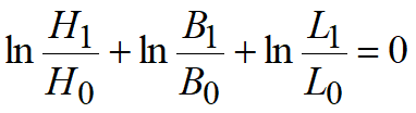
therefore
after taking the logarithm
The sum in the derived expression represents the logarithmic (true) strains in three mutually perpendicular directions. Thus, at plastic deformation the sum of the true strains in three mutually perpendicular directions is always equal to zero.
Plastic deformation rates possess the same property:
This equation is also called the material incompressibility. There is an important implication of the volume stability law. At plastic deformation one of the strain rates (true strains) has a sign opposite to the signs of the other two, and its absolute value is equal to their sum, i.e. its absolute value is the maximum one. |
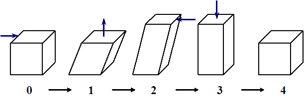
Finite and infinitesimal strains cannot describe to the full extent the possible metal properties deviations resulting from the large plastic deformations in non-monotonic processes. Monotonic processes imply the deformation processes, in which all strain rate tensor components change in proportion to a single parameter. Near monotonic processes are the ones in which the strain rate tensor components retain their signs. Thus, sensu G.A. Smirnov-Alyaev, in a monotonic process the direction of the fastest elongation (stretching) of the material fibre always coincides with the direction of total elongation (stretching) for the previous process. For example, material internal and external fibres are deformed monotonically at large radius bending. Let's consider a non-monotonic deformation process consisting of shear, tension, backward shear, and compression. It is possible to select stage parameters, such that the finite form of an element at the finite stage won't differ from the initial one.
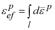
This process is non-monotonic. If the deformations at every stage are plastic, then the material properties remain unchanged. However, finite (as well as small) strain tensor in the finite process stage will be equal to zero by definition. Equality to zero will also be observed for effective strain. Thus, it is impossible to determine this process influence on the material properties by means of finite strain factors. For complex characterization of the process impact on the material properties an "effective" (equivalent, accumulated) plastic strain is used. It is defined as a sum of the effective plastic strain increments that is calculated along the material point motion trajectory:
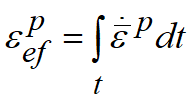
Effective plastic strain is also defined with the "equivalent plastic strain rate" (plastic strain rate intensity). Here the integration is performed along the material point motion trajectory.
|
In QForm UK postprocessor the user can display the following fields: •in workpiece:
Notes: 1. Hencky finite strain fields are available only after adding and computation of standard subroutine Strain Tensor on the tab Subroutines after simulation is complete. 2. Volumetric strain is calculated only for non compact material simulation. •in the tool:
|
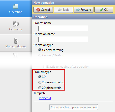
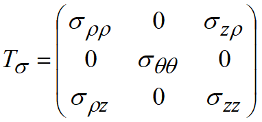
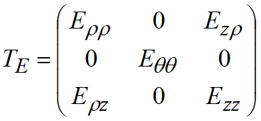
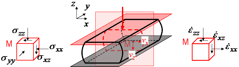
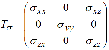
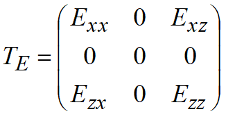
During simulation of the forming processes a stress and deformed state of the whole workpiece is usually considered (3D task). The accuracy and the duration of analysis depends on the number of nodes and finite elements. For a general case of stress and deformed state this number can be rather large. At the same time for a number of tasks a good approximation can be achieved by considering the stress and deformed state in the workpiece cross-sectional plane (2D task). Among these tasks are the deformation of forged parts with elongated axis (plane deformation) and axisymmetric forged parts (axisymmetric deformation).
|
||||||||||||||||||||||||||||||||||||||||||||||||||||||||||||||||||||||||||||||||||||||||||||||||||||||||||||||||||||||||||||||||||||||||||||||||||||||||||||||