In the course of plastic deformation the workpiece changes its shape under the action of external forces. As a result of external forces action internal forces occur in the deformed body. The measure of internal forces is stress.
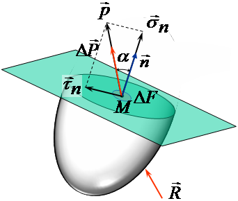
In order to determine the stress vector in a surface element passing through the body material point М the body is divided with an imaginary surface passing through the point М into two parts. One part is mentally rejected, and its influence on the rest part is substituted with a system of internal forces. Allow a small area of this section be influenced by the internal force ΔΡ. Generally the direction of force action does not coincide with the direction of plane normal n.
The vector of stress acting in the small area passing through the point М is the limit
It is possible to draw an infinite number of planes through the point, and any of them will have its own direction of normal. The magnitude of stress will depend on the direction of normal to elementary area. Stress vector can be decomposed into normal sn and shear τn stress
It should be understood that stress is a mathematical abstraction used to describe the internal forces in a continuum medium. |
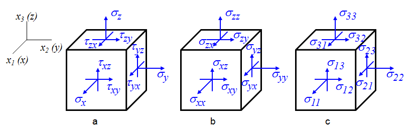
Stress state in a point is determined with a set of normal and shear stresses in 3 mutually perpendicular surface elements passing though this point. Let's denote the coordinate axes as x1, x2, x3 (near are shown the corresponding traditional designations x,y,z). Let's draw through a stressed point М the three planes parallel to coordinate axes. Now lets's draw a parallelepiped which edges we consider to be infinitesimal. Every face of this parallelepiped represents a coordinate plane.
We will decompose the stress applied to every surface into three components: normal stress σ that is perpendicular to surface, and two shear stresses τ located in the plane of surface and directed along the coordinate axes (fig. a). The rule of stress subscripting: the first subscript indicates the direction of the normal to surface, and the second - the direction of axis to which the vector is projected. For normal stresses the direction of normal to surface and the direction of action coincide, therefore, for brevity, instead of, e.g. σxx is used a designation σx. An alternative method of stress designation and subscripting (fig b): all the components of stresses in the coordinate planes (both normal and shear) are denoted by ℘. If the subscripts coincide, e.g. σyy, then the stress is normal, if not, e.g. σyz, then the stress is tangential. In technical literature a numeric notation is often to shorten the record used (fig.c). That is done by associating the axes x, y, z with designations x1, x2, x3. In this case at set of stresses in thee coordinate planes can be denoted as σij, where i, j take the values 1,2,3. The set of stresses in three mutually perpendicular planes going through the stressed point of continuum medium forms the symmetric tensor of second-order called the stress tensor. Depending on the used subscripting the stress tensor takes the form:
If the stress components in three mutually perpendicular planes going through the point are known, it is possible to determine the stress components in any other coordinate plane passing through this point. In QForm UK is used the momentless theory which implies that the stress tensor is symmetric. components located symmetric about its principal diagonal are equal. |
Stress σm that is equal to one third of the sum of stresses located on the main diagonal of stress tensor is called the mean (average) stress (average normal stress), and the quantity p that is equal to it in value but opposite in sign is called the hydrostatic pressure.
A tensor derived from the stress tensor by subtracting the average normal stress from the diagonal components is called the stress deviator.
In short, the components of the stress deviator can be written as:
where dij - Kronecker delta (equals to 1 for i = j, equals to 0 for the rest of cases), i,j=1,2,3 Stress deviator stipulates the change of body shape without change of its volume. |
A complex characteristic of stress is called effective stress:
In the case of uniaxial tension
Consequently, for uniaxial tension the effective stress is equal to the normal stress applied along the specimen axis:
Superscript tens is for English word "tension" |

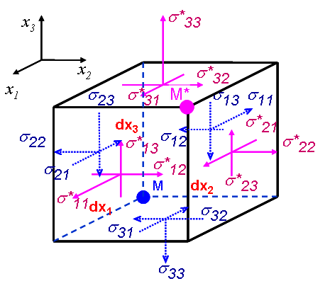
In general case the stress state is inhomogeneous. In other words, it is different for two points, even if they are close to each other. The result of this is the stress gradients causing the reasons for metal flow. Let's consider a stress state in two points, M and M*, located at an infinitesimal distance from each other.
The stresses in parallel planes change in proportion to stress gradient, e.g..
With neglect of bulk forces the body should be in a state of equilibrium. Then the sum of projections of forces exerted on the parallelepiped to every coordinate axis should be equal to zero
Finally, the system of differential equations of equilibrium in Cartesian coordinates takes a form:
In short form these equations are written as follows:
The equations discussed above are the equations of equilibrium. In reality, metal particles move with certain acceleration.Also the metal is influenced by the bulk forces (e.g. gravity). In a general case the equations of equilibrium are transformed to the equations of motion and then take the form:
where gi are the components of the vector of specific bulk forces (e.g., gravity acceleration), vi - velocity vector components, ρ - density. In the majority of real-world problems it is possible to neglect the accelerations and especially bulk forces, and the motion equations become the equations of equilibrium. The equations of motion are usually considered for high-speed processes, for example, for magnetic pulse forging. |
In QForm UK postprocessor the user can display the fields of the following stresses in workpiece and tool:
Notes: Stress tensor components, principal stresses, Lode-Nadai parameter and Cockroft fracture criterion are available for preview in workpiece only after a preliminary calculation in a standard subroutine. Lode-Nadai parameter is determined from the formula:
Cockroft fracture criterion:
Here
|