In this section typical examples of initial 2D and 3D geometry for various technological processes are considered.
Two-dimensional closed contours of tools and workpieces are used for 2D simulation. The loading of 2D geometry into the project is performed from the files with the extension *.dxf, prepared in third-party CAD systems, or files with the extension *.crs, designed in the geometry editor QDraft.
Three-dimensional tools and workpieces bodies are used for 3D simulation. Loading 3D geometry into a project is done from files with the extension *.shl or *.qshape , prepared in the geometry editor QShape , which is designed to import solid or surface geometry from files with the extension *.step And *.igs (deprecated format, limited support. It is recommended to use *.step files) and transforming them into finite element models.
It is also possible to import geometry in QForm UK directly from files with the extension *.step. In this case, the correction of geometry defects and the creation of a surface mesh are carried out automatically. If necessary, the user may do additional corrections in the created finite element model using the geometry editor QShape. Direct import is suitable when using good quality 3D geometry without critical defects.
When the workpiece is forged in the round dies, the metal flows evenly in all directions from the axis of symmetry. This metal flow is called Аxisymmetric. In this case, it is sufficient to consider the forming only in the axial section plane of the forging. For the 2D simulation of the axisymmetric task, it is necessary to prepare closed contours of dies and workpiece in the axial section plane:
|
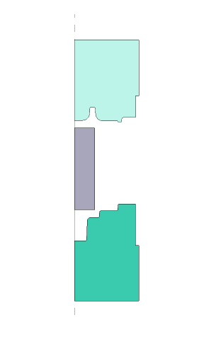
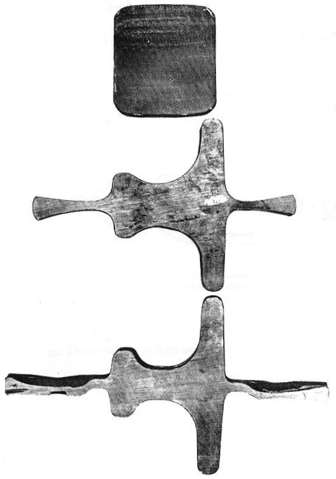
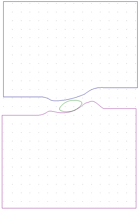
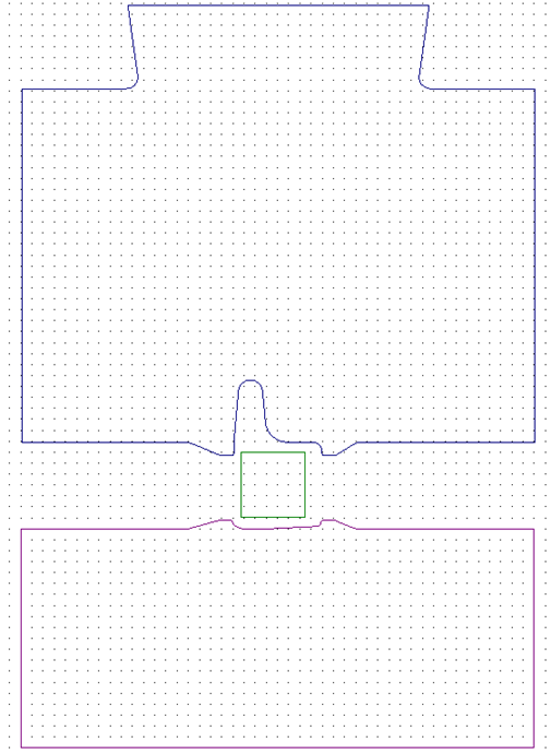
A typical example of Plain strain deformation can be observed in section planes of long products: for example, beams or blades. If the forging has a considerable length, the metal flow in the longitudinal direction can be neglected and the deformation can be considered only in the characteristic transversal section sections:
The figures below are presented the typical 2D drawings of the section planes for the simulation of elongated forgings prepared in QDraft:
|
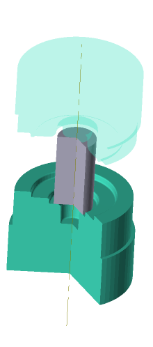
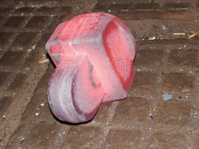
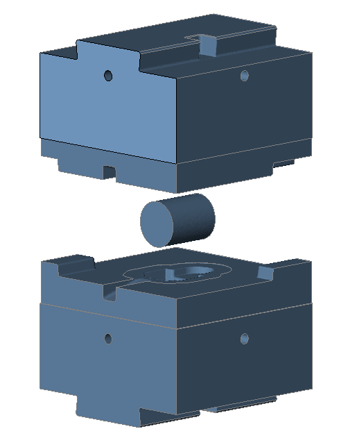
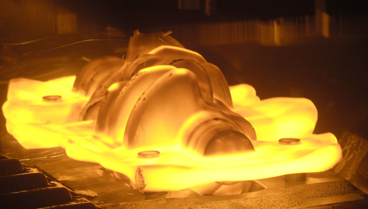
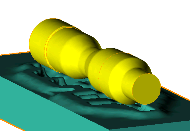
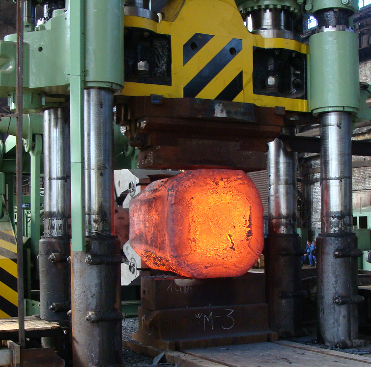
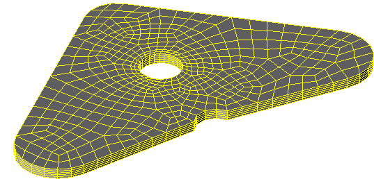
The figures below show the examples of initial geometry for the 3D bulk forging simulation:
To perform the flash trimming, the geometry of the 3D clipping surface, outside or inside of which the material will be removed at a particular simulation step, must additionally be loaded or created. The figure below shows an example of the initial geometry for the crankshaft forging simulation:
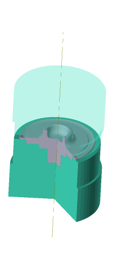
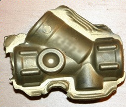
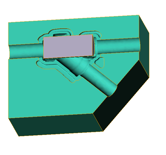
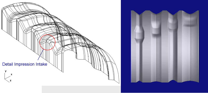
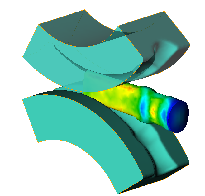
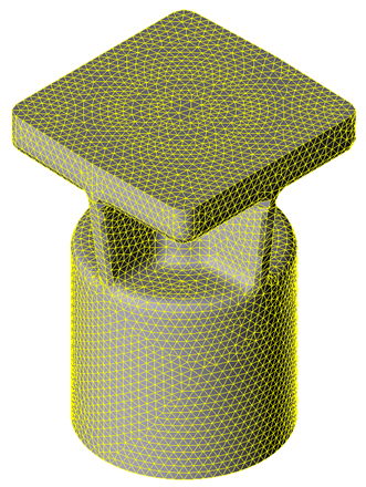
An example of the initial geometry for a copper fitting forging simulation is presented in the figure below:
|
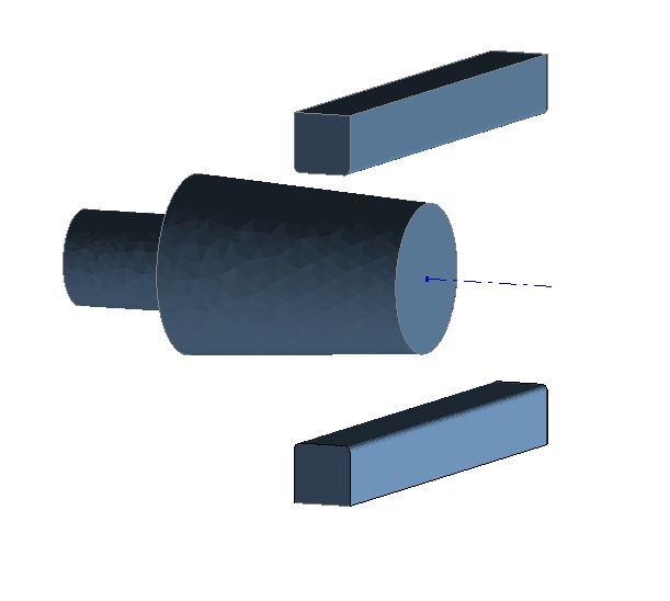
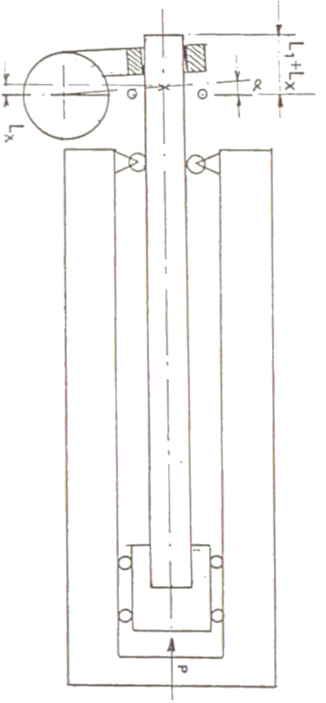
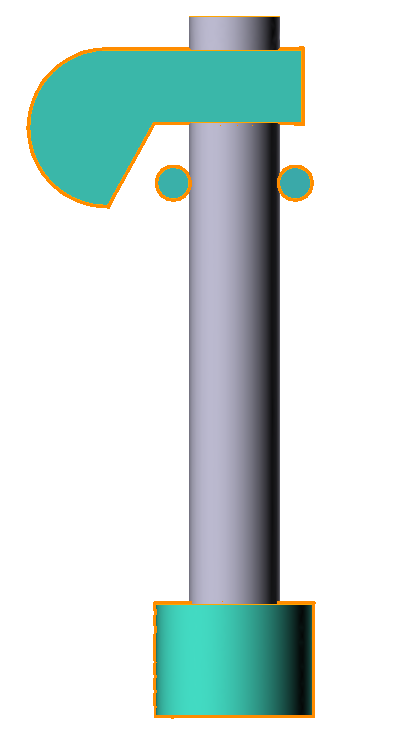
Axis must be defined for the workpiece to provide automatic canting and displacement of the billet during the simulation of the open die forging:
|
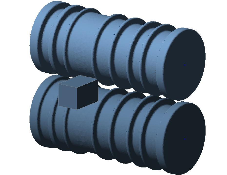
Axes must be defined for all rotating tools for the reverse rolling simulation. The axis must be also defined for the workpiece to set the canting angles and the movements between the passes:
|

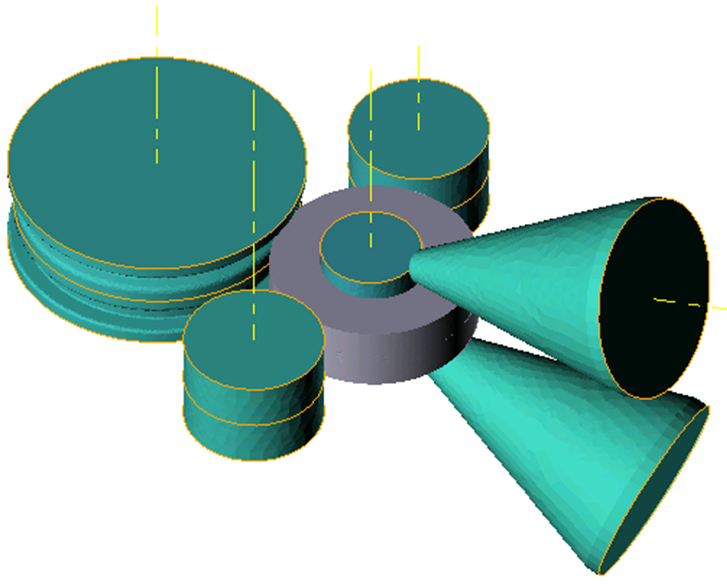
| 3D ring rolling |
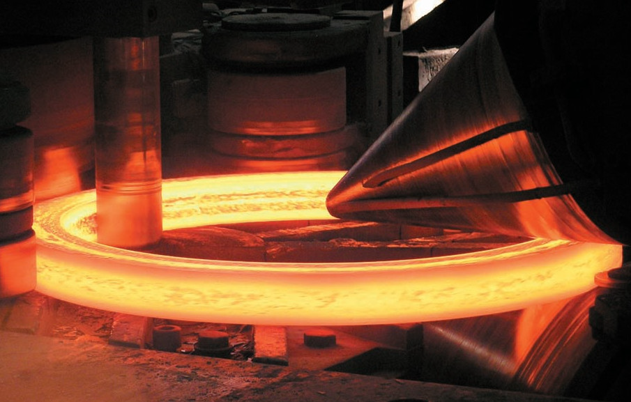
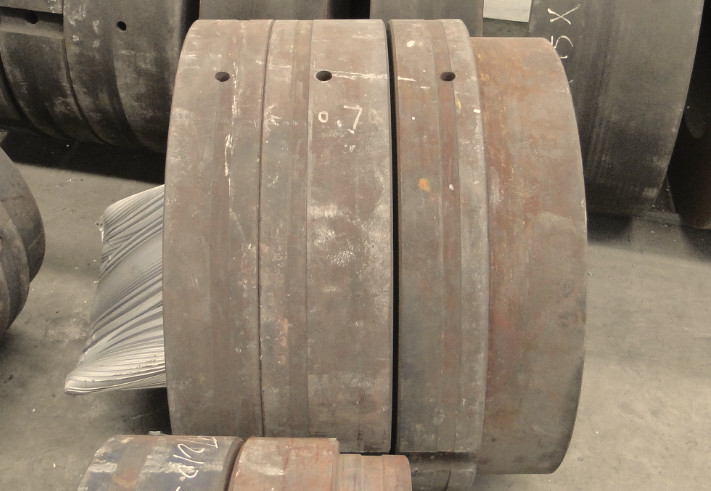
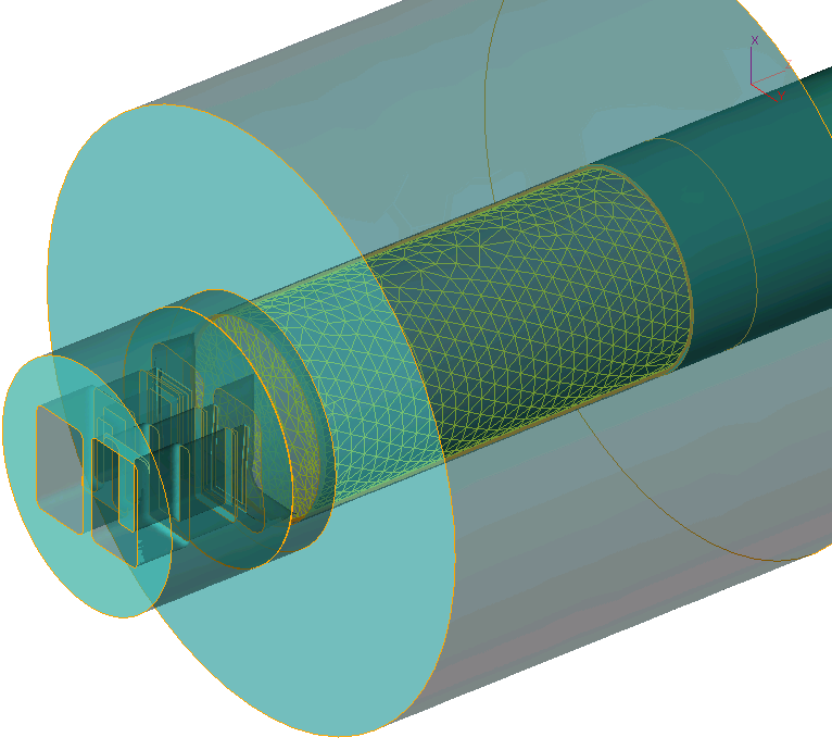
An example of the initial geometry for the simulation of the ring rolling is shown below. Axes must be defined for all rotating tools:
|
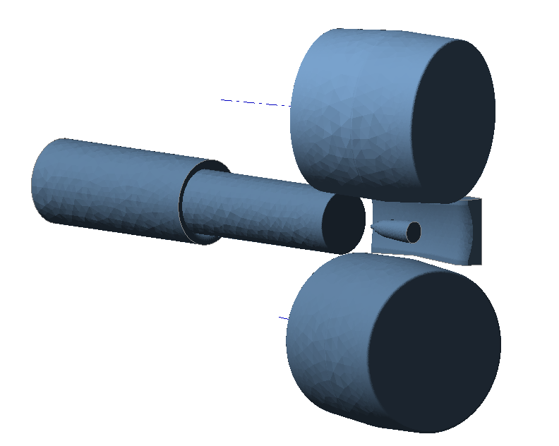
To simulate the cross rolling it is necessary to set the axes of the rotating rolls:
|
The principles of geometry preparation for extrusion simulation are described in the separate documentation module. QForm UK Extrusion:
|
QForm UKcan simulate a wide variety of metal forming processes. Some of them are shown here for example:
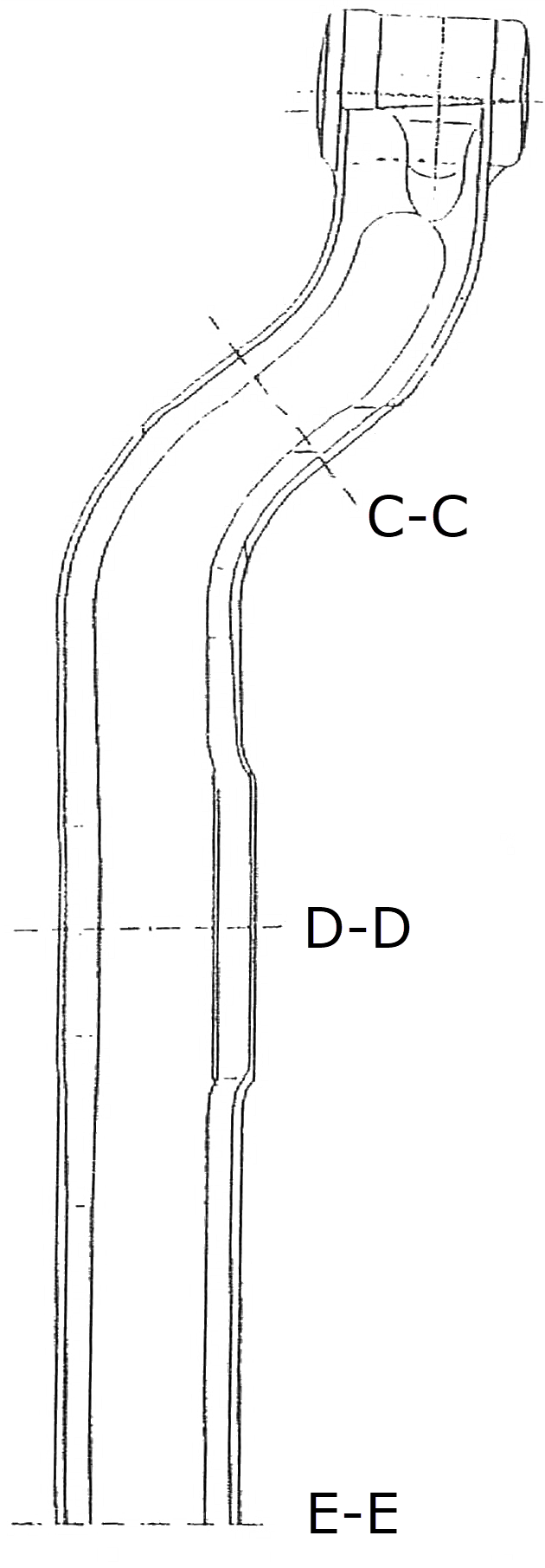
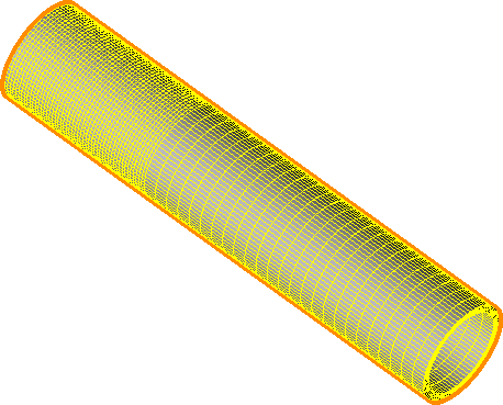
Bending of pipes
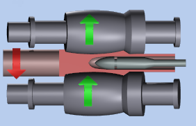
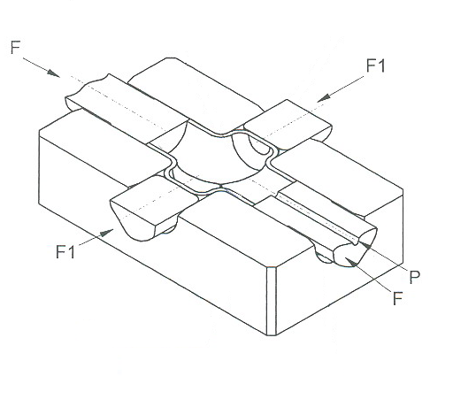
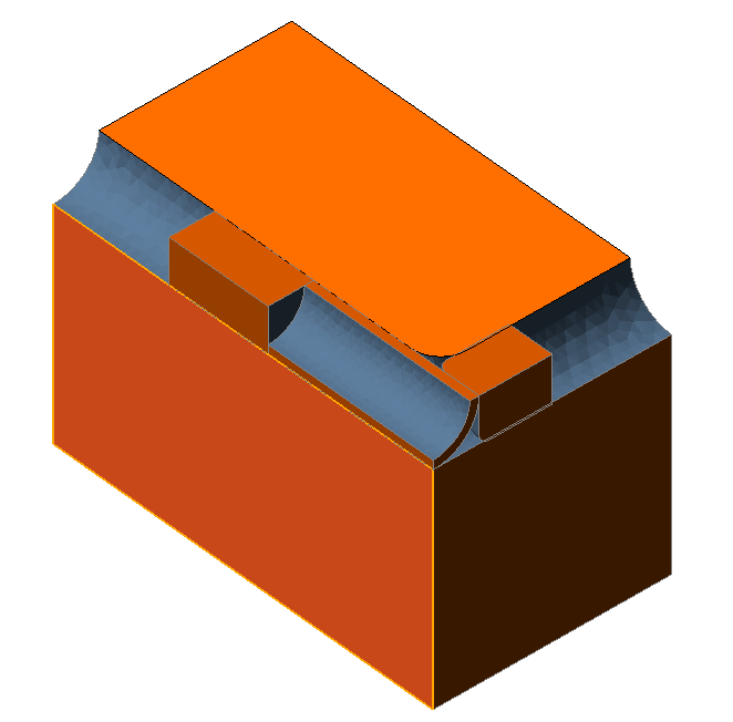
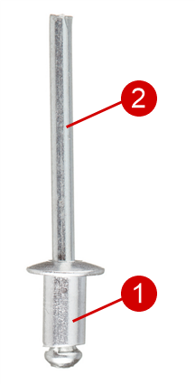
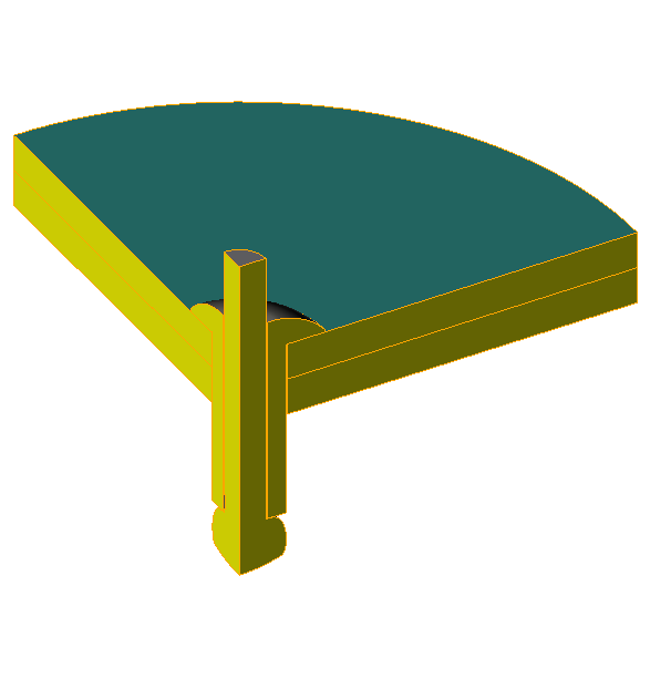
Coupled elastic-plastic deformation of several bodies The QForm UK ensures simulation of plastic deformation of several workpieces made of different materials at once. The initial geometry for the simulation of the aluminum rivet with a steel core affixing of two metal sheets is shown below:
|
Import from specialized programs designed to generate finite element meshes:
QForm Extrusion Die Designer (QExDD) – is the tool designing system for extrusion of aluminum alloys:
VeraCAD VeraCad © Eratz Ingenieur Büro http://www.eratz.de/en/eratz-engineering
ProCAST ProCAST © ESI Group http://www.esi-group.com/
|


See also: