The principle of hydroforming is that the pipe is placed in the cavity of the die, the configuration of which corresponds to the configuration of the part being formed. Dies, which are generally split longitudinally, are closed when the press slide starts moving.
In the process of hydro forming a load from two punches, moving along the pipe axis, is acting on the pipe ends. The method of manufacturing T–bends, four-way unions and elbows by hydroplastic processing provides for using of load holders to prevent the pipe wall rupture. Under internal pressure and axial compression force the workpiece material goes into a plastic state, the pipe wall starts bending and fills the die cavity forming a finished part. To prevent rupture of the retraction wall there is rigid tool providing support with a certain force that defines the retraction height and thickness of the retraction wall. The process scheme is shown in the figure below.
|
A - T-bend; B - Load holder; C - Axial upsetting punch; D - Die. |

An example of hydroforming simulation of T-bend 6х0.8 is considered. The parameters of the hydroforming of this product are below.
The initial workpiece is a pipe (diameter D= 6 mm, length L=55 mm, wall thickness S=0.8 mm).
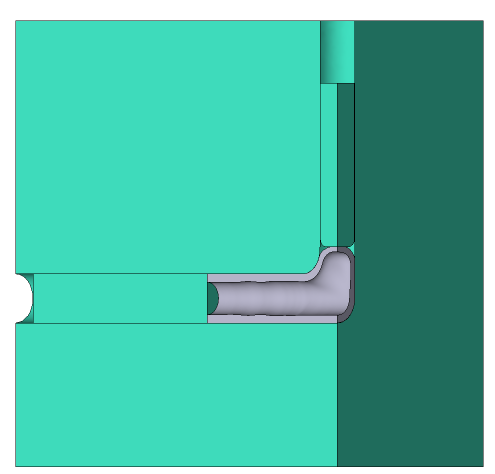
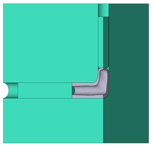
Forming is carried out in two steps. The figure below shows the initial and intermediate (between operations) dimensions of the workpiece
|
A - Workpiece; B - First action; C - Final action. |

To reduce the simulation time, two planes of symmetry have been used in this example. Thus, not the whole T-bend but only its quarter is being simulated.
Operation 1 |
Operation 2 |
|
|
Initial data
Operation 1 |
||
Operation |
Operation type |
General forming |
Additional parameters |
With thermal process |
|
Problem type |
3D |
|
Geometry |
Load from file |
hydro_forming.shl |
Workpiece parameters |
Material |
Steels\Ni - NiCr - NiCrMo\X10CrNiTi18-10 (1-6903) cold |
Temperature |
20 ˚С |
|
Tool parameters |
Drive |
Tool 1 - Fixed drive +OZ Tool 2 - Hydraulic press 0.45 MN, velocity 1.305 mm/s Tool 3 - Load holder 1.5 kN |
Lubricant |
Tools 1, 2, 3 - water-soluble emulsion (hydroforming) |
|
Material |
Tools 1, 2, 3 - H13HRC50 |
|
Temperature |
Tools 1, 2, 3 - 20 ˚С |
|
Put in contact |
Tools 1, 2, 3 - do not put in contact |
|
Coupled deformation |
Not |
|
Heat transfer to workpiece |
Simple |
|
Stop conditions |
Time |
3.83 s |
Boundary conditions |
Environment |
Air 20 ˚С |
Pressure |
Workpiece inner surface, refer to Table 1 (1 operation) |
|
Blows |
Number of blows |
1 |
Cooling in air |
0 s |
|
Cooling on tool |
0 s |
|
Simulation parameters |
The maximum element size for workpiece |
0.2 mm |
Operation 2 |
||
Operation |
Operation type |
General forming |
Additional parameters |
With thermal process |
|
Problem type |
3D |
|
Geometry |
Inherit from previous operation |
Workpiece, Tools 1, 2, 3 |
Workpiece parameters |
Material |
Inherited from previous operation |
Temperature |
20 ˚С |
|
Tool parameters |
Drive |
Tool 1 - Fixed drive +OZ Tool 2 - Hydraulic press 0.45 MN, velocity 1.305 mm/s Tool 3 - Load holder 1.5 kN |
Lubricant |
Tools 1, 2, 3 - water-soluble emulsion (hydroforming) |
|
Material |
Tools 1, 2, 3 - H13HRC50 |
|
Temperature |
Tools 1, 2, 3 - 20 ˚С |
|
Put in contact |
Tools 1, 2, 3 - Do not put in contact |
|
Coupled deformation |
Not |
|
Heat transfer to workpiece |
Simple |
|
Stop conditions |
Time |
3.83 s |
Boundary conditions |
Environment |
Air 20 ˚С |
Pressure |
Workpiece inner surface, refer to Table 1 (2 operation) |
|
Blows |
Number of blows |
1 |
Cooling in air |
0 s |
|
Cooling on tool |
0 s |
|
Simulation parameters |
The maximum element size for workpiece |
0.2 mm |
Tab. 1 |
|||
1st operation in the chain |
2nd operation in the chain |
||
Time, s |
Pressure, MPa |
Time, s |
Pressure, MPa |
0 |
0 |
0 |
0 |
0.5 |
50 |
0.6 |
50 |
0.9 |
100 |
1.1 |
100 |
1.2 |
150 |
1.4 |
150 |
1.6 |
200 |
1.8 |
200 |
2.0 |
250 |
2.2 |
250 |
2.4 |
300 |
2.6 |
300 |
2.8 |
350 |
3.0 |
350 |
1.Click Create new process

2.In the Operation tab select Operation type - General forming, With thermal process, Problem type - 3D. Click Forward.

3.In the tab Geometry click Load from file and specify the path to the geometry file C:\QForm UK\12.0.1\geometry\hydro_forming\hydro_forming.shl. The uploaded geometry will appear on screen. Click Forward.

4.In the Workpiece parameters tab you need to set the material and workpiece temperature. Click next to Material[Select...].
In the database window that opens, select the material Steels\Ni - NiCr - NiCrMo\X10CrNiTi18-10 (1-6903) cold and double-click on it, after which the material will appear in the tabWorkpiece parameters.
Set the workpiece temperature to 20˚C. Click Forward.

5.In the tab Tool parameters it is necessary to set the drive type, temperature and lubricant for each tool. In this example Tool 1 - the die, Tool 2 - axial upsetting punch, Tool 3 - load holder.
Next to Drive-Tool 1 click [Select...], the equipment database window will open. Select equipment Fixed drives\+OZ and double-click on it, after which the selected drive will appear next to Drive-Tool 1.
Tool 2 - axial upsetting punch, which moves in the direction of the OX axes at a velocity of 1.305 mm/s and a maximum load of 0 MN. Next to Drive-Tool 2 click [Select...], you have to create a new equipment in the equipment database window. Click Create and set the equipment parameters as shown on the figure below

After that click Save as... and set a name for the new equipment, for example, hydro 1.305 mm-sec. In the database directory Project file the created equipment will appear, double click on it, after that the selected drive will appear next to Drive- Tool 2.
Next to Drive-Tool 3 click [Select...]. Tool 3 - the back- pressure punch that moves in the direction of the OZ axes under the action of the workpieces pressure . The pressure force is 1.5 kN. Create a new equipment as shown in the image below

After that, click Save as... and set a name for the new equipment, for example, holder 1.5 kN.In the database directory Project file the created equipment will appear, double click on it, after that the selected drive will appear next to Drive-Tool 3.
Next to Lubricant click [Select...] and in the database window, create a new lubricant (Levanov's friction Law friction factor 0.1, Levanov coefficient 1.25, heat transfer coefficient 40000 W/m2 ·K, pause coefficient 0.05), save it as hydroforming. After that, assign the created lubricant by double click. Lubricant will appear immediately for all tools.
Opposite Material click [Select...] and double click to set the material H13HRC50 (according to AISI). The material will appear immediately for all tools. Next to Temperature set tool temperature to 20 °C.
In step Put in contact you have to select Do not put in contact. Otherwise, before origin the simulation , the tools will be moved in the appropriate directions until they come into contact with the workpiece.
After setting all the data, the window Tools parameters will look like the picture below. Click Forward

6.In the tab Stop conditions process time have to be set. Click Time.
After that, enter the time (3.83 s). Click Forward

7.In the tab Boundary conditions it is necessary to set the pressure inside the workpiece. Select object Workpiece, and a list of boundary conditions will appear below. Click Pressure

Next, you need to select the domain shape. Click Surface.
On the menu How to select elements - By faces, then holding down the keyShift, click the inner surface of the tube. The selected plain surface will change a color. Click OK

After that, you need to set the pressure value. In the drop down menu Value type select Table

Press on Table, then click on [Select...] a database window will open where a table of pressure values depend on time should be created. Click Create. In the graph Value type select Table function and enter the pressure value from the Table 1 (refer to initial data). After that click Save and set the table name, for example, hydro action1. Click the button Assign or double click on the table name, then close the database window

After assigning the boundary conditions click Forward
8.In the tab Blows all remains unchanged. Click Forward
9.In the Simulation Parameters tab, you need to set the maximum element size equal to 25-30% of the wall thickness of the workpiece. To do this, go to the Workpiece mesh tab, change the method of setting the Element Size, set the Maximum element size parameter to 0.2 mm. Click OK

10.Click on the button Simulation![]() , and the program will ask to save the project. Enter the project a name and click OK. The simulation will start after that.
, and the program will ask to save the project. Enter the project a name and click OK. The simulation will start after that.
11.When simulation of the operation is finished, open the Project tab and press Add an operation to a chain
|
Information |
The second operation should be added only after the first operation has been calculated! |
|

12.In the Operation tab select Operation type - General forming, With thermal process, Problem type - 3D. Click Forward.
13.In the tab Geometry click Inherit from previous operation, in the new open window, check the boxes for all tools. Click OK. The Geometry of the tools will appear on screen, with the position of the tools corresponding to the final position in the first operation.Click Forward

14.In the tab Workpiece parameters set the workpiece temperature to 20 °C. Next to Temperature it is should be selected Set in this operation and set the temperature 20 °C. Click Forward

15.In the Tool parameters tab set everything like for the first operation. Click Forward
16.In the tab Stop conditions set the time to 3.83 s as for the first operation. Click Forward
17.In the tab Boundary conditions it is necessary to set the pressure inside the workpiece. Similarly to the first operation, set the pressure on the inner surface of the workpiece using the data in Table. 1 (refer to Initial data). Highlight a table hydro action1, click Save as... and enter a name hydro action2. After that, change the value in the new table in accordance with the initial data. Click Assign and close the database window

18.In the tab Blows all remains unchanged. Click Forward
19.In the tab Simulation parameters Set the adaptation parameters as for the first operation. Click OK
20.Save the project and click the button Simulation![]()