Saddling (also known as saddle forging or mandrel forging) is performed using an auxiliary tool instead of the lower die, consisting of two supports (E) and a cylinder mandrel (C). The heated and pre-punched workpiece (A) is deformed by the upper flat or spherical narrow die (B) on the mandrel (C), which in this case acts as the lower die. After each hammer or press blow, the workpiece is rotated by a certain angle. As a result of such deformation, the thickness of the rings (D) decreases, the width increases slightly, the cross cut plane also decreases and, consequently, its diameter increases. At the beginning of rolling, a mandrel with the diameter approximately equal to 0.9 of the diameter of the hole in the workpiece is used, then mandrels of a larger diameter are used. After obtaining the basic required dimensions, the resulting irregularities are smoothed out, giving the forging the required final dimensions. Saddling is used in the production of various rings, shells, gear rims and other similar parts. The figure below shows a saddling process.

An example of simulating saddling of a large workpiece is shown, consisting of two operations: upsetting a cylinder workpiece (2000x2600), piercing a hole (⌀1050 mm) and saddling. In order to reduce the simulation time, a symmetry plane was specified in the example. Thus, the shaping of only half of the workpieces is considered.
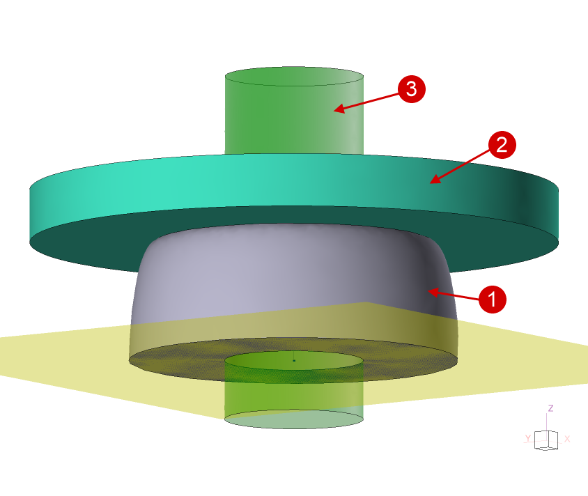
Operation 1 (1) - workpiece, (2) - punch, (3) - clipping surface |
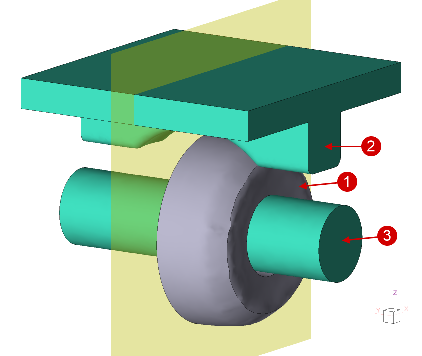
Operation 2 (1) - workpiece, (2) - die, (3) - mandrel |
|
|
Initial data
Operation 1 |
||
Operation |
Operation type |
General forming |
Additional parameters |
With thermal process |
|
Problem type |
3D |
|
Geometry |
Load from file |
saddling_op1.shl, saddling_piercing_surface.shl |
Workpiece parameters |
Material |
Steels\Carbon steels\C10 (1-0301) |
Temperature |
1200˚С |
|
Tool parameters |
Drive |
Tool 1 - Hydraulic press 150 MN, velocity 10 mm/s, direct drive |
Lubricant |
Tool 1 - Graphite-water (Hot forging/Steels/Graphite + Water) |
|
Material |
Tool 1 - H13HRC50 |
|
Temperature |
Tool 1 - 20˚С |
|
Put in contact |
Tool 1 - with a move backward first |
|
Coupled deformation |
No |
|
Heat transfer to workpiece |
Simple |
|
Stop conditions |
Tool stroke |
Tool 1 - 400 mm |
Boundary conditions |
Environment |
Air 20˚С |
Blows |
Number of blows |
1 |
Cooling in air |
600 s |
|
Cooling on tool |
0 s |
|
Simulation parameters |
Maximum element size of workpieces element |
90 mm |
Operation 2 |
||
Operation |
Operation type |
General forming |
Additional parameters |
With thermal process consideration |
|
Problem type |
3D |
|
Geometry |
Load from file |
saddling_op2.shl |
Workpiece parameters |
Material |
Inherited |
Temperature |
Inherited |
|
Tool parameters |
Drive |
Tool 1 - Hydraulic press 150 MN, velocity 20 mm/s, direct drive Tool 2 - Fixed drive +OZ |
Lubricant |
Tools 1, 2 - Graphite-water (Hot forging/Steels/Graphite + Water) |
|
Material |
Tools 1, 2 - H13HRC50 |
|
Temperature |
Tools 1, 2 - 20˚С |
|
Put in contact |
Tool 1 - with a move backward first Tool 2 - with a move backward to contact |
|
Coupled deformation |
No |
|
Heat transfer to workpiece |
Simple |
|
Stop conditions |
Distance |
Individually for each blow |
Boundary conditions |
Environment |
Air 20˚С |
Blows |
Table |
15 blows, 30˚ rotation , cooling in air 10 s. |
Simulation parameters |
Maximum element size of workpieces elements |
90 mm |
1.Click Create a new process
2.In the tab Operation select Operation type - General forming, With thermal process, Problem type - 3D. Click Forward.
3.In the tab Geometry click Load from file and specify the path to the geometry file saddling_op1.shl (default:C:\QForm UK\12.0.1\geometry\saddling\saddling_op1.shl).
The loaded geometry will appear on screen, the symmetry plane and the rotation axis of the workpiece are already set in QShape, so there is no need to set them.
Click Load from file and specify the path to the file saddling_piercing_surface.shl. The Clipping surface will appear on screen. Select Clipping surface- Plain surface 1, and the properties of clipping surface will appear below. Specify Remove the material - Inside clipping surface, When to clip - After current operation. Click Forward.

4.In the tab Workpiece parameters the material and workpiece temperatures should be set. Click on Material[Select...]
In the opened database window, select the material Steels\Carbon steels\C10 (1‑0301) and double-click on it, after that the material will appear in the tab Workpiece parameters.
Set the workpiece temperature to 1200˚С. Click Forward
5.In the tab Tool parameters the drive type, temperature and lubricant for each tool should be set. In a real process the bottom plate would be stationary, but since horizontal symmetry is used here it is assumed that the bottom tool moves towards the top one. To take this into account, you need to set the press velocity to be half that of a real press. In our case, a 150 MN press with a velocity of 20 mm/s is used, therefore, for this operation, it is necessary to create a 150 MN hydraulic press with a velocity of 10 mm/s.
Click on Drive[Select...], in the equipment database window you need to create new equipment. To do this, click Create and set the equipment parameters as shown in the figure below.

After that, click Save and give a name to the new equipment, for example, 150MN 10mm per s. In the database directory Project file the created equipment will appear, double-click on it, after that the selected drive will appear opposite to Drive.
Opposite to Lubricant click [Select...]and double click to set lubricant Hot forging/Steels/Graphite + Water(graphite-water).
Opposite to Material click [Select...] and double click to set the material H13 HRC50.
After setting all the data, the window Tools parameters will look like the picture below. Click Forward

6.In the tab Stop conditions the tool stroke should be set. Click Tool stroke.
Opposite to Tool shift specify the tool shift value (400 mm) and select the tool for which the condition is set. Click Forward

7.In the tab Boundary conditions all remains unchanged. Click Forward
8.In the tab Blows set the cooling in air time to 600 s, the rest remains unchanged. Click Forward
9.In the tab Simulation parametersmaximum element size should be set equal to 90 mm. This is the optimal element size for simulation of open die forging of large billets. Click OK

10.Click on the button Simulation![]() , and the software will propose to save the project. Enter a name for the project and click yes. After this, the simulation will begin.
, and the software will propose to save the project. Enter a name for the project and click yes. After this, the simulation will begin.

11.Once the operation is calculated, open the tab Project and select Operation 1. Click below Add operation to chain

12.In the tab Operation select Operation type - General forming with thermal process, Problem type - 3D. Click Forward
13.In the tab Geometry click Load from file and specify the path to the geometry file saddling_op2.shl.
The loaded geometry will appear on screen. It is necessary to rotate the workpiece 90 degrees clockwise around axis X. To do this, click on Positioning, click on the button Rotation, selectworkpiece and rotate it 90 degrees around axis X as shown in the figure below.
|
Important |
Set the coordinates of the initial and finals positions of the specifies grip to (0;0;0). |
|

It is also necessary to move the workpiece down so that it does not intersect with the mandrel. Click on thePositioning, select the Workpieceand move it along the Z axis to the required distance. Closepositioning window .

Since the symmetry plane does not rotate with the workpiece, it must be deleted and set again. Select from the list Plane 1 and in the window Properties click Delete.

After that, click Set the symmetry plane and, holding down the key Alt, Specify the position of the new symmetry planes by clicking on the corresponding edge of the workpiece. Click Done, inwindow Geometry the line Plane 1will appear again.

Click Forward
14.In the tab Workpiece parameters all remains unchanged: the workpiece and its temperature are inherited from the first operation. Click Forward
15.In the tab Tool parameters set the drive for Tool 1 - a 150 MN hydraulic press with velocity of 20 mm/s (it is necessary to create new equipment, as described for the first operation, but the velocity this time is not 10 mm/s, but 20 mm/s, since the symmetry plane is vertical), for Tool 2 - fixed drive+OZ. Specify the lubricant and material of the tools. In the column Put in contact - with a move backward to contact for Tool 2. Click Forward

16.In the tab Stop conditions the finish distance between the tools should be set. Click Distance.
After that, specify the value of the finish distance (430 mm) and select the tools between which it is set. Click Forward
17.In the tab Boundary conditions all is unchanged. Click Forward
18.In the tab Blows set the amount of blows (15), 15 lines will appear, in each you need to enter the cooling in air time (10 s) and the rotation angle of the workpieces between blows (30 °). Click Forward
|
Information |
The rotate angle parameter appears if the workpiece axis is specified . In the example, the axis is predefined when the geometry is created. If this parameter is not present, specify the axis. |
|

19.In the tab Simulation parameters set the adaptation parameters (maximum element size 90 mm). Click OK
20.Save the project and click the button Simulation![]()
See also: