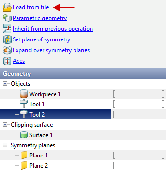
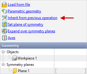
In the tab Geometry the loading of geometrical objects, setting of their properties and positioning are carried out. It contains info about all loaded and created objects, symmetry planes and axes:
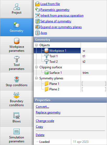
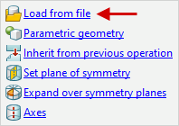
The geometry is loading by the command Load from file. You can load to the project: •geometry for 2D- simulation- from files *.dxf prepared in a CAD system, or from files *.crs, created in the editor QDraft. • geometry for 3D- simulation - from files *.step prepared in a CAD-system, or from files *.qshape, *.shl, created in the editor QShape. • workpiece mesh with fields of temperature and accumulated strains for 3D- simulation - from file *.qmesh3d, exported from another project. • volumetric finite element mesh of objects created in specialized applications from files *.ntl and *.unv. With help of these formats it is also possible to import calculation fields and volumetric mesh from casting simulation software, such as ProCASTorMagma. The calculated fields in this case can be loaded to the corresponding object help the feature Import fields. • geometry 2D-cut cutting - from files *.dxf or *.crs. • geometry 3D- clipping surface - from files *.step, *.shl or *.qshapes. • geometry for 3D simulation - from *.dxf files prepared in a CAD system and then deployed in 3D. All supported file extensions can be viewed from the drop-down list in the file explorer pop-up window:
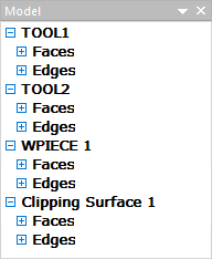
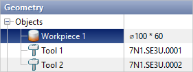
Geometric objects can be loaded into the project both together (from one file) and separately (from different files). In this case, you should pay special attention to the fact that the numbering and type of loaded objects correspond to the type and numbering assigned in the geometry editors QDraft or QShape. It is demonstrated below how the list of objects looks like after loading the geometry from *.shl-file. Objects types and numbers are defined in the geometry editor QShape:
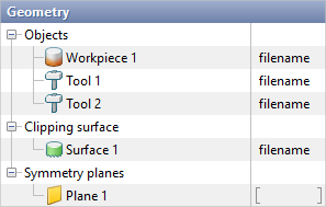
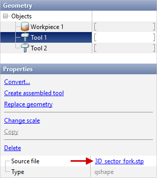
In the column on the right, in front of the loaded objects, the file name without the extension from which the geometry was loaded is indicated. If symmetry planes were specified in the geometry file, they will be displayed in the list Symmetry planes. If necessary, you can write any alternative object name in the right column:
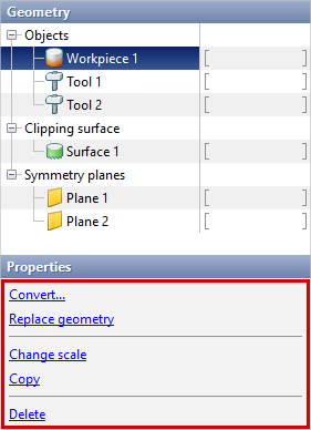
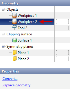
The alternative name of the object is also displayed and can be changed in Object tree. If select any object, then in the window Properties advanced features will appear with which you can convert the type of object, replace its geometry or delete it:
Some window features Properties are duplicated in the context menu, which can be used with the right mouse button on the tab Geometry, in Results view window or in Object tree. |

| Objects converting and copying objects |
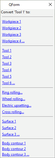
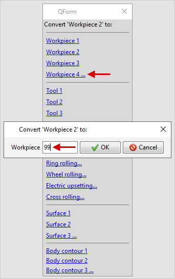
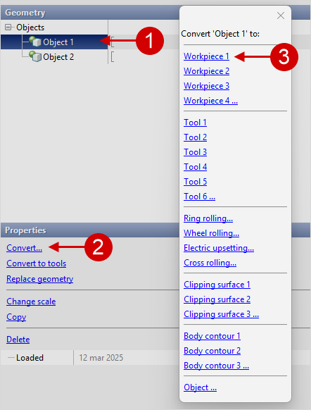
After loading the geometry from file, you can change the type and number of any object. To do this, select the corresponding object in the list, press Convert... and in the window that opens, change the type of this object and the number, for example:
The Converting is also available from the context menu from the right mouse button on the object on the tab Geometry, in Results view window or in Object tree. You can set any object number, since the amount of objects for simulation is unlimited:
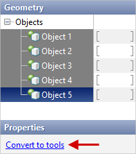
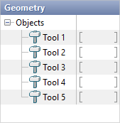
To quickly converting multiple objects into tools, there is an feature Convert tools. Required by holding the key ctrl select several objects and in the window Properties press Convert to tools:
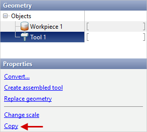
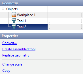
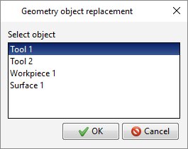
Converting to tools is also available from the context menu from the right mouse button on a group of objects in Results view window or in Object tree. In order to copy any object, you need to select the desired object in the list and in the window Properties press Copy. After that, in the window that opens, should be set the type of the new object and the number. If there is more than one object in the specified geometry file, then a window will appear and you need to select the desired object which replace the original object:
|
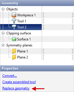
In order to replace geometry of any object, it is necessary to select the required object in the list and in the window Properties press Replace geometry... After that, you need to specify the file from which the new geometry will be taken. If there is more than one object in the specified geometry file, then a window will appear and you need to select the desired object which replace the original object:
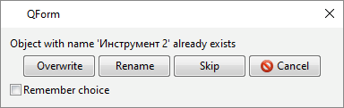
Replacing the geometry is also available from the context menu from the right mouse button on the object on the tab Geometry, in Results view window or in Object tree. The geometry can be converted in other way. Let's look at an example when the geometry has already loaded into the project . The project has Workpiece 1, Tool 1, Tool 2. If execute the command Load from file and specify the path to the new geometry file, which for example contains objects WPIECE, TOOL1, TOOL2, TOOL3, then a dialog box will appear in case the objects names match in which you need to select actions for objects with matching names:
Overwrite - replaces the geometry with the geometry of the object of the same name from file the geometry file. Rename - in this case, the geometry is not replaced, the object of the same name must be convert to another object. Skip - object is not loaded from file. Cancel - geometry loading is cancelled. Feature Remember choice applies the selection to all subsequent conflicting objects in the file. |
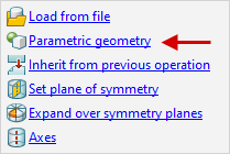
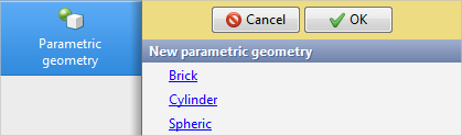
Team Parametric geometry allows you to create primitives. This command is only available in the source data preparation mode. For Problem type: 3D the following geometric shapes are available: brick, cylinder, sphere. For Problem type: 2D axisymmetric or 2D plane strain only creating a rectangular object is available.
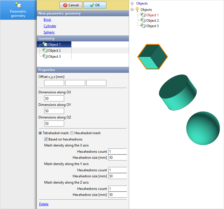
This feature allows you to quickly create simple workpieces and tools without the use of CAD applications. You have to specify properties for the objects you create. For all types of geometric shapes, the ability to specify an offset is available, which allows you to make fast positioning of created objects. Next, you need to specify the dimensions of the created object. Mesh options are also available for cylinder and rectangular. For a rectangular, you have to specify the dimensions along the X, Y, and Z axes. By default, the rectangular uses a tetrahedral mesh. It is possible to switch the mesh to a tetrahedral mesh based on hexahedrons and to a hexahedral mesh. In the first case, a mesh of hexahedrons will be created, each of them will be divided into 6 tetrahedrons. In the second case, there will be no division into hexahedrons. In both cases it is possible to specify the amount of hexahedral elements or the element size along each of the axes. When one of these parameters is specified, the other parameter will be automatically recalculated. A similar approach is used for a rectangular in 2D problems. Offset along the X and Z axes is possible. You have to specify the dimensions along the same axes. Instead of tetrahedral and hexahedral elements, triangular and rectangular elements. At the same time, the feature Based on rectangulars creates a mesh of rectangular elements, each such element is divided into 2 triangles after.
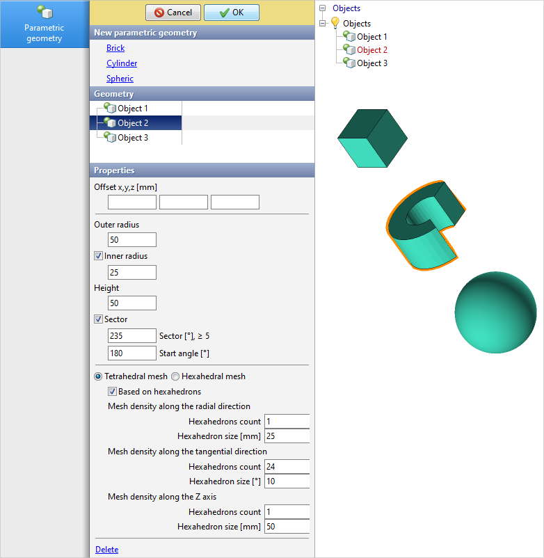
For a cylinder, you have to specify the outer radius and height of the cylinder. Optionally, it is possible to create a through hole with an indication of the inner radius. It is also possible to create a sector. To do this, you need to activate the corresponding feature and enter the sector angle. Optionally, it is possible to specify the start angle of the sector. If there are 2 symmetry planes, for the feature Sector will also be available Use symmetry planes, which automatic calculates the required angle value. By default, a tetrahedral mesh is also used for the cylinder. It is possible to switch the mesh to a tetrahedral mesh based on hexahedrons and to a hexahedral mesh. The mesh setup is similar to a brick, except that a cylinder coordinate system is used instead of a brick coordinate system.
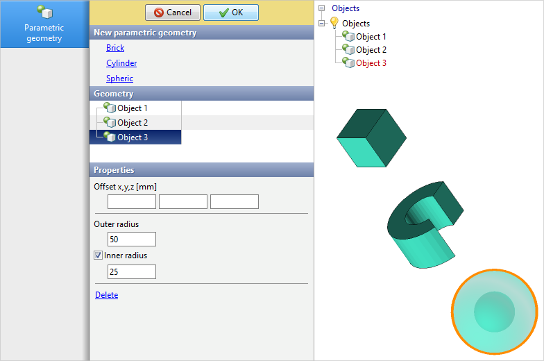
For a sphere, you have to specify an outer radius. Optionally, it is possible to create an internal sphere with an indication of the inner radius.
When the desired offset parameters and objects properties are specified, you have to press the button OK to confirm the creation of objects. After creating parametric objects, they can be edited in the same tab. Editing is also available only in Initial data mode.
See also: |
||||
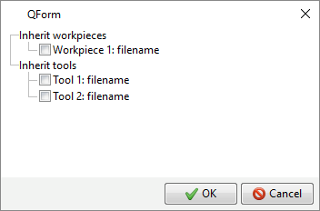
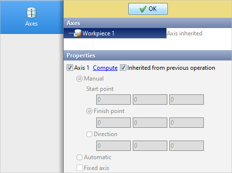
Option Inherit from previous operation available starting from the second operation of the technological chain. It is used if it is necessary to inherit some geometric objects from the previous operation. By default, only the geometry of workpiece is inherited , taking into account its deformation:
If it is necessary to inherit the geometry of the tools, then check the boxes opposite to the corresponding tools. The initial position of the inherited objects corresponds to their position on the last calculated record of the previous operation. |
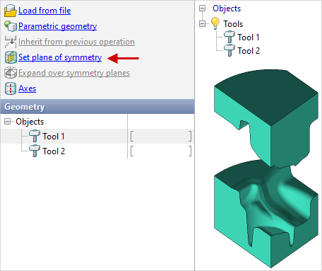
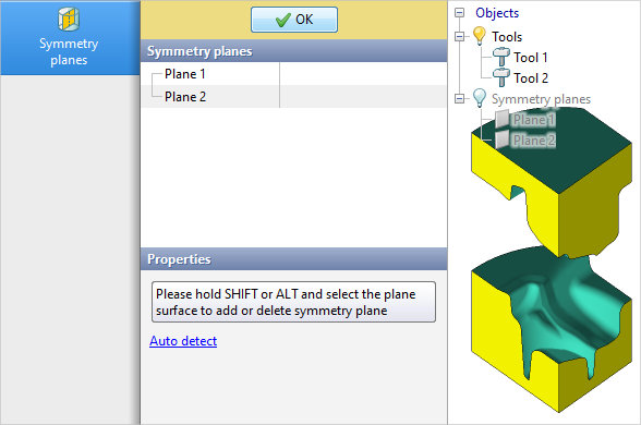
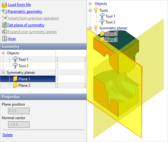
Symmetry planes can be set in two ways: in the editor QShape or directly in QForm UK with the help of command Set symmetry planes. A tab will open Symmetry planes. It is necessary by holding the key Alt or Shift use the mouse to select one or more faces on which you want to set symmetry planes. To delete the symmetry plane you have to also select the face while holding the key Alt or Shift. Auto detect is also available, which auto detects symmetry planes if the angle between objects faces is less than or equal to 90 degrees. To complete the creation or removal of symmetry planes, click OK:
The specified symmetry planes will appear in the tab Geometry and in the object tree in the list of symmetry planes. Removing any symmetry planes is possible without opening a tab Symmetry planes. To do this, select the symmetry plane in the tab Geometry, in the workspace or in the object tree and click Delete on the panel Properties. Removing is also possible through the right-click context menu.
Removing is also available from the context menu from the right mouse button on the object on the tab Geometry or in Object tree.
See also: |
||||||||||


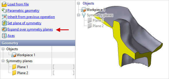
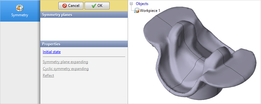
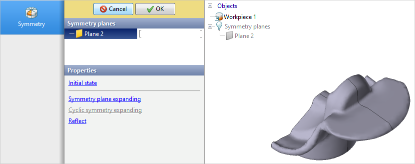
Option Expand over symmetry planes available starting from the second operation of the technological chain. It is used when you want to move from operation with some amount symmetry planes to an operation with less amount of symmetry planes, or if you want to reflect objects to use new symmetry planes. By using this command tab will open Symmetry.
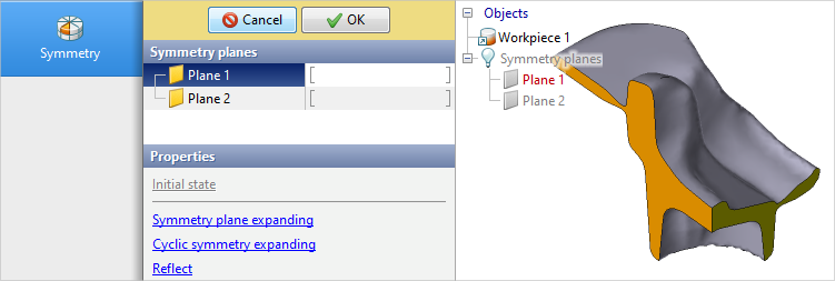
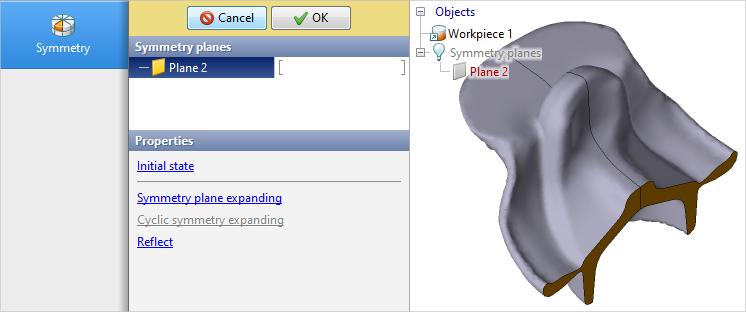
Selecting the symmetry plane, the feature Symmetry planes expanding allows you to build the missing part of the workpieces. After building on the selected plane, this plane will be deleted.
Feature Cyclic symmetry expanding available in the presence of 2 symmetry planes and allows you to complete the full body using the sector, the angle of which does not exceed 90 degrees.
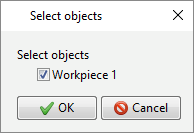
Feature Reflect allows you to build a mirror copy of the object on the other side of the selected symmetry plane. A pop-up window will appear with a selecting objects to reflect.
To confirm the changes, click the button OK. To cancel changes, press the button. Cancel or use the feature Return to original state. This feature also allows you to discard changes even after you confirm them. To use this feature, you need to use the command again Expand over symmetry planes. |
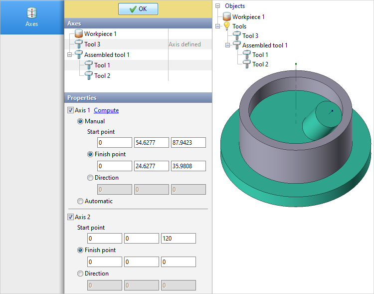
Axes for 3D objects can be set in two ways: in the graphics editor QShape or directly to QForm UK help the commands Axes. After running this command, a tab will open Axes, in which you have to select the object you want to set the axes. You can specify one axis for a workpiece. You can specify one or two axes for a tool.
To specify an axes, you have to specify either a initial point and end point or a initial point and direction. The initial point of the axes is shown in the workspace. The initial point helps to determine the direction of rotation around the axis. If the location of the axes in space is such that the initial point is far from the observer, then the rotation of the object counterclockwise around this axes will correspond to the concept of counterclockwise rotation in QForm UK. For rotation bodies there is also an feature Compute, which automatic selects the necessary values. When selecting an assembled tool, the feature is available Compute all axes. This feature activates and calculates Axis 1 for all components of the assembled tool. The resulting axes length only affects the display of that axes in the workspace. Usually the axes move along with the objects.
For a workpiece, it is possible to fix the axis by the feature Fixed axis. If this option is activated, the axis position will not be recalculated during the simulation. After setting the axes, pressOKfor confirmation. When inheriting objects, it is possible to inherit axes. By default, when creating subsequent operation, the workpieces axis is inherited. If necessary, you can set the axis again by unchecking Inherited from previous operation.
See also: |
||||||||
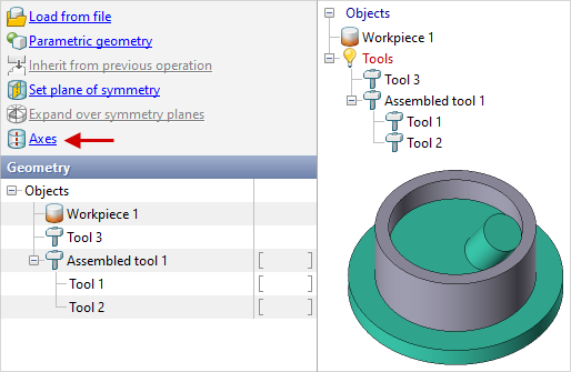
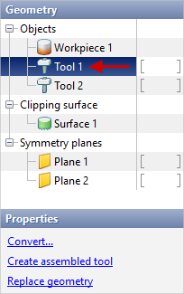
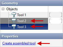
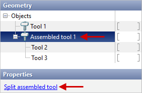
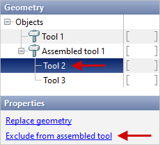
to create an assembled tool, hold down the key ctrl, select several tools in the list of objects and in the window Properties press Create assembled tool. To split an assembled tool, select it and in the window Properties press Split assembled tool. If you need to remove any tool from an assembled tool, select this tool and in the window Properties press Exclude from assembled tool.
These feature are also available from the right-click context menu in Results view window or in Object tree. |
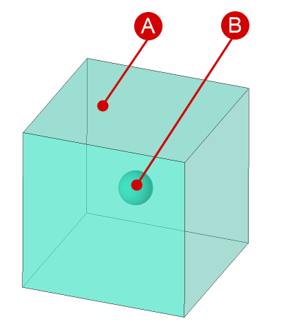
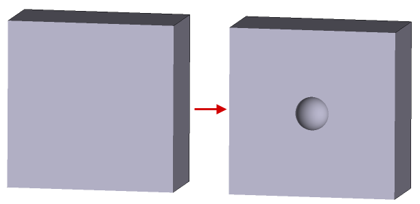
The structure of the metal is not uniform in most cases. Regardless of the technology and method of casting the metal, voids called pores are observed in the finished ingots.
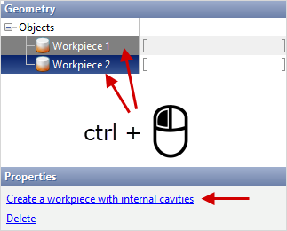
2. Sequentially convert both objects to the workpiece type. 3. Select both workpieces with the pressed ctrl key and in the properties find the Create a workpiece with internal cavities command.
4. As a result, a new workpiece is created, obtained by subtracting two bodies. Unnecessary objects must be removed before starting the simulation. |
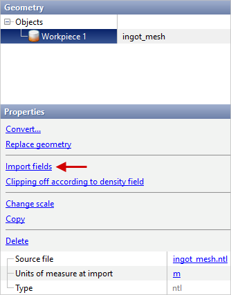
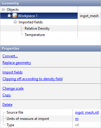
Import of calculated fields from casting simulation applications such as ProCAST and Magma is carried out as follows: 1. Export of the calculation mesh from the casting simulation applications to *.ntl- or *.unv- file. The exported mesh have to be intended for finite element computations. 2. Export of the calculated fields values of temperature and relative density in each node from the casting simulation applications to files *.ntl, *.pda or *.unv. 3. Import of calculation mesh into QForm UK from files *.ntl or *.unv with help of the commands Load from file. 4. Import of calculated fields to an imported mesh from files *.ntl, *.pda or *.unv with the help of the feature Import fields. Fields can only be imported in the Initial data mode:
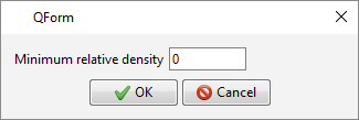
Additionally, it is possible to execute the removal of elements whose density value is lower than the user defined value. To do this, use the feature Clipping off according to density field and specify the threshold value.
|
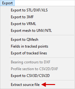
There are several ways to extract the source geometry file. To extract the source geometry source file of an object, you have to first select the object whose geometry you want to extract. You can select an object directly in the tab Geometry in Results view window or in Object tree. When an object is selected, in the tab Geometry in the window Properties you need to click on the file name or on the tab Export in the Main menu press Extract source file. From 3D objects *.step or *.igs-files are extracted, the original file is extracted from 2D objects *.dxf- file or *.crs- file that can be observed in the editor QDraft:
If the object was created with the command Parametric geometry or directly in the editor QShape with help of feature Create object, during selection of such an object the command Extract source file does not appear. |
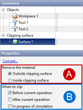
The Clipping surface is designed to remove fragments of the calculation mesh. The clipping surface is a geometric object whose shape, location, and options determine which zone of the workpieces will be removed. The clipping surface, like any other object, can be loaded by the commands Load from file, created with the commands Parametric geometry, created or prepared by geometry editors QDraft or QShape or converted with the commands Convert... from another object. •clipping surface for 2D- simulation loaded from *.dxf- a file prepared in any CAD system, or *.crs- file prepared in 2D geometry editor QDraft. •clipping surface for 3D- simulation loaded from files *.step, prepared in any CAD system or from files *.shl or *.qshape prepared in the geometry editor QShape. • clipping surface in the Sheet bulk forming module, the clipping surface is loaded in *.dxf format and positioned according to the technology. It is important to note that the contour must be closed and have no cavities. If clipping needs to be performed along multiple contours, they must be loaded separately, and the material removal parameters must be selected correctly.
The surface will appear in the list of cutting objects after loading. It have to be select in the window Properties specify:
It is necessary to pay attention to the fact that at a certain stage of simulation the operation (Before current operation, After current operation, In process of simulation) only one clipping surface can be active. To delete the clipping surface, select it in the list, then in the window Properties press Delete. |