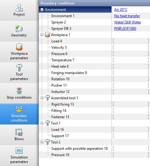
In the tab Boundary conditions various connections are defined between the modeling objects and their environment. This allows us to take into account the influence of the environment or other systems on the processes under study.
By default, in the tab Boundary conditions only the environment is indicated Air 20C. However, for some processes simulation, the environment may differ from the default environment, or for objects of type Workpiece and Tool advanced boundary conditions may need to be defined.
Changing environment parameters
To simulation heating or cooling processes, it may be necessary to overwrite the environment, for example, with a fit by of a heating furnace or a quenching environment, respectively. For this need to click on the environment Air 20C, which is specified by default. The database window will appear Environments, in which it is necessary to create a new fit by or select an existing fit by with the required set of environment parameters.
Adding local boundary conditions
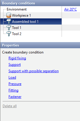
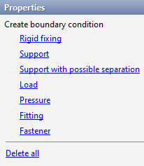
To add a boundary condition, you must select the object for which you want to create a boundary condition. Next, in the window Properties you must select the boundary condition that you want to create, and then set the acting domain of this boundary condition.
Domain and principle of actions of domain of boundary conditions
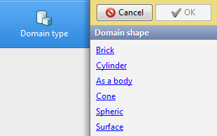
After selecting a boundary condition, you need to select a control method the domain of this boundary condition in the panel Domain type:
|
|
|
Available domain type for most boundary conditions for 3D simulation |
|
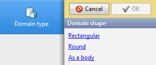
Available domain type for most boundary conditions for 2D simulation |
Acting domain of boundary conditions, except Fitting and Fastener, are specified either help 3D domain and 2D contours, or by specifying surfaces (3D objects only).
Once the domain shape is selected, you need to configure the array in the panel Domain parameters. The properties will differ depending on the type of the selected domain.
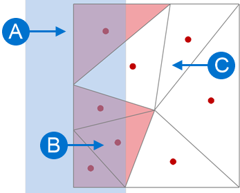
When creating a boundary conditions domain, its center is at point with zero coordinates. Types of domain for specifying boundary conditions in 3D problems
Types of domain for specifying boundary conditions in 2D problems
|
|||||||||||||||||||


Domain typeSurfaceallows you to select the plain surface of a 3D object to which the boundary condition will be applied. Setting the plain surface of actions of boundary conditions must be done at the simulation stage Initial data. Ways to selecting elements: •By faces While holding down the key Shift, you need to select the plain surface of the object to which the boundary condition will be applied. This will highlight the plain surface bounded by the edges. If no such surfaces, then the entire plain surface of the object will be selected. You can select multiple surfaces at once. If a plain surface is assigned incorrectly, you can discard the selection by clicking the mouse while holding down the key Alt:
•By elements While holding down the key Shift, you need to select the surface elements of the object to which the boundary condition will be applied. This will select a plain surface fragment bounded by the edges of the selected finite element. If you assign an element by mistake, you can discard the selection by clicking the mouse while holding down the key Alt:
•By color When work with this method, on Toolbar the feature is auto enabled Show color imported from CAD system. This method works similar to the method By faces, however, this method allows you to immediately select all elements painted by the CAD system in the same color:
|
||||


To change the parameters of the domain of specified boundary conditions, you need to go to the tab Boundary conditions select the required condition. After that in the window Properties it will be possible to change the dimensions of the domain shape of the selected condition by clicking Edit. An alternative way is to call the command Edit size from the context menu when right-clicking on an array:

|
Information |
The selected domain type cannot be change; to do this, you will need to create the boundary condition again. |
|
To delete a boundary condition that is not required, you must also select a condition on the tab Boundary conditions and in the window Properties press Delete. An alternative way is to call the command Delete from the context menu when you right-click on the array.
If you need to create several identical boundary conditions, then the selected condition can be copy. To do this you need to go to the tab Boundary conditions and in the window Properties press Copy or call the same command in the context menu when you right-click on the array.
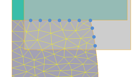
Depending on the control method and the type of boundary conditions, they can be applied: •to the surface nodes of the finite element mesh; •to the surface elements of the finite element mesh; •to volumetric elements of a finite element mesh. Local parameters environment parameters only affect surface nodes that are not in contact with other objects. Boundary conditions Velocity, Forging manipulator, Rotation, Pusher, Rigid fixing, Support, Support with possible separation act on all surface nodes of elements that fall within the specified acting domain of the boundary condition:
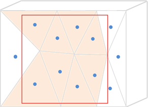
Boundary conditions An effort, Pressure, Heat rate, Heat rate per area act on all surface elements whose centers fall within the specified acting domain of the boundary conditions. Surface elements in this case are the sides of triangles on the surface of a body in a 2D simulation or the faces of tetrahedrons on the surface of a body in a 3D simulation:
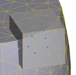
Boundary condition Heat rate per unit volume acts on elements in a 2D simulation or in a 3D simulation whose centers fall within the acting domain of the boundary condition:
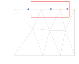
Boundary condition Inductor unlike Heat rate per unit volume affects elements in a 2D-simulation or in a 3D-simulation, even if the centers of these elements do not fall within the acting domain of the boundary condition. For a condition to act on an element, it is sufficient that one of the nodes of the element is in domain of the boundary condition.
|
|||||||||||||||||||||||||
Boundary conditions properties
Once the acting domain of a boundary condition is defined, you need to specify the properties of the boundary condition.
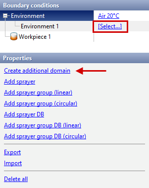
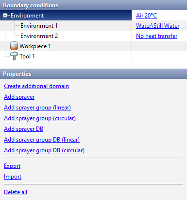
To set local parameters, click on the line Environment in the window Boundary conditions and in the window Properties select Create additional domain:
After creating the local conditions domain, the line appears Environment, opposite which you need to click [Select...]. The database window will appear Environments, in which it is necessary to create or select the required set of environment parameters. Further, additional adjustment of the actions time and movement of the environment is possible.
It is possible to export the created local environment condition - additional array, selected fit by and all options. To do this in the window Properties you need to press the button Export and save the file *.qdat. To export all local environment condition at once, you need to in the window Boundary conditions select Environment, then in the window Properties select Export and save the file *.qdat.
To import previously created files *.qdat needed in the window Boundary conditions select Environment, then in the window Properties select Import. In addition to advanced domain of the environment, it is also possible to create sprayers. |
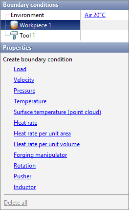
To set local parameters, click on the line Workpiece in the window Boundary conditions and in the window Properties select the boundary condition you want to create:
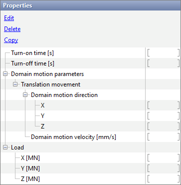
After creating a boundary condition domain, a line will appear with the name of the selected condition. Next, additional configuration of the parameters of the created condition is required. For all boundary conditions related to the workpiece except Surface temperature (point cloud), it is possible to configure the turn-on and turn-off time, the parameters of the translation movement of the domain.
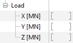
Next you need to configure the parameters that define each boundary condition: •Load – determines the magnitude and direction of the force acting on surface elements. The given load is divided by the total area of the surface elements, the center of which falls within the boundary condition domain, and the resulting specific force is applied to each of these elements:
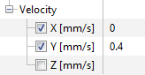
•Velocity – determines the velocity and movement direction of surface nodes falling within the boundary condition domain:
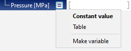
•Pressure – determines the amount of pressure acting on surface elements. A specified pressure is applied to each surface element whose center falls within the boundary condition domain. It is possible to set a constant pressure value or a pressure dependence over time:
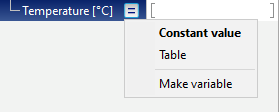
•Temperature – determines the temperature of surface nodes. It is possible to set a constant temperature value or a temperature dependence over time:
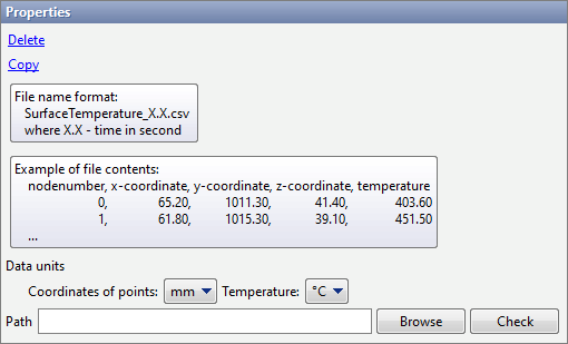
•Surface temperature (point cloud) – boundary condition intended for importing the results of thermal computations and setting the temperature distribution on the surface of the workpieces in accordance with the downloaded results. The boundary condition allows you to import *.csv files with coordinates of surface nodes and corresponding temperature values at each node.
To import files, you must either manual enter the path to the directory containing *.csv files, or select a directory help the button Browse. Button Check allows the programm to find *.csv files in the specified directory. If no suitable files in the directory, a message will be displayed Files not found. If the directory contains matching files, they will be downloaded and a message will be displayed Uploaded N files, where N - amount of detected files.
•Heat rate –determines the total heat rate acting on the surface elements of the workpieces, the center of which falls within the array of the boundary condition.
•Heat rate per unit area – determines the surface density of the heat rate acting on the surface elements of the workpieces, the center of which is in the array of the boundary condition.
•Heat rate per unit volume – determines the volumetric heat rate density acting on the volumetric elements of the workpieces, the center of which falls within the boundary condition array.
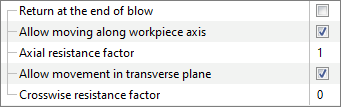
•Forging manipulator– boundary condition designed to hold the free end of the workpieces. This boundary condition simulates a manipulator that, during the strain process, holds the workpiece parallel to the initial position of its axes.
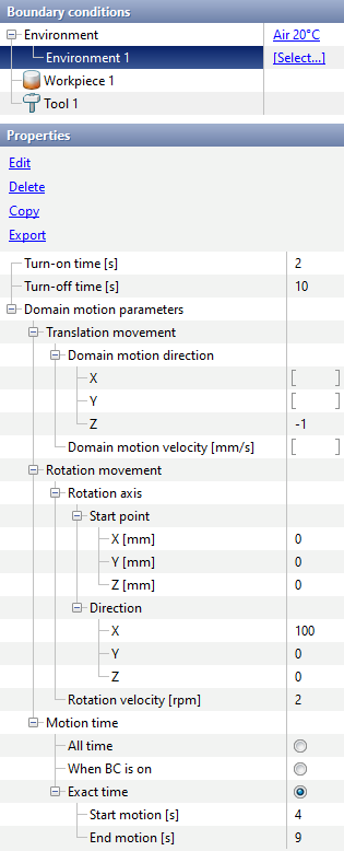
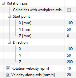
Feature Return at the end of blow compensates for the displacement of the workpieces due to the blow and returns it to its original position. Feature Allow moving along workpieces axis allows the surface nodes of the workpieces located in domain of the boundary condition to move in the direction along the axis. Axial resistance factor multiplier determines the force that prevents the movement of surface nodes along the axis. QForm UK determines the resistance load based on the weight of the workpieces, which is subject to the boundary condition. The multiplier allows you to adjust the work of the boundary condition if, as a result of the simulation, insufficient or excessive displacement of the restrained workpieces along the axes is observed. Feature Allow movement in transverse plane allows surface nodes of the workpieces located in domain of the boundary condition to move in directions perpendicular to the axis. Crosswise resistance factor determines the force that prevents the movement of surface nodes along the axis.QForm UK determines the resistance load based on the weight of the workpieces, which is subject to the boundary condition. The multiplier allows you to adjust the work of the boundary condition if, as a result of the simulation , insufficient or excessive displacement of the held workpieces perpendicular to the axis is observed. Boundary condition Forging manipulator recommended for simulation open die forging processes, for example, simulation cogging. •Rotation – boundary the boundary condition is intended to specify the rotation of the workpieces with possible translation movement along the rotation axis. The boundary condition acts on all surface nodes of the workpieces falling within a given domain:
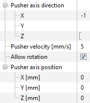
Rotation axis workpieces can be specified in one of two ways: 1. If it is already specified in the tab Geometry, you just need to activate the parameter in the properties of the boundary condition Coincides with workpiece axis 2. If it is unset in the tab Geometry, you must specify the coordinates Start point rotation axis and Direction axis. If the parameters value Rotation velocity or Velocity along axis are not specified, they will be obtained from the solution at each simulation step. In this case, the boundary condition Rotation works like a hinge type support. •Pusher – boundary condition designed to push a workpieces in a user defined direction. This boundary condition prohibits the displacement of the surface nodes for which it is defined in planes perpendicular to the pushing direction:
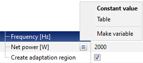
When you enable the feature Allow rotation, the pushed workpiece can additionally rotate at a velocity imparted to it as a result of contact with the tool. In this case, it is additionally necessary to specify a point to specify the axis around which the workpiece will rotate. •Inductor – boundary condition simulating the working body of induction heating installations. This boundary condition was developed to simulation the processes of heating a workpieces by intense electromagnetic radiation. As parameters of the inductor in the field Frequency it is should be set the frequency of the heating installation current in the field Net power it is necessary to indicate the average net power. It is possible to set a constant value of frequency and net power or tabular dependences of these parameters on time:
To use the boundary condition, it is necessary to set an additional array so that it covers the plain surface and a certain depth of the workpieces.
|
||||||||||||||||||||||||||||||||||||||||
To set local parameters, click on the line Tool or Assembled tool in the window Boundary conditions and in the window Properties select the boundary condition you want to create:
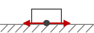
Boundary conditions Rigid fixing, Support, Support with possible separation, Load and Pressure will require the creation of an additional domain. After creating a boundary condition domain, a line will appear with the name of the selected condition. For boundary conditions Fitting and Fastener a line with the name of the selected condition will appear without creating an additional domain. Next, you may need to additionally configure the parameters of the created condition. •Rigid fixing – finite element mesh nodes to which this boundary condition is applied are prohibited from displacement in any direction •Support – finite element mesh to which this boundary condition is applied are only allowed to displacement tangentially to the tool plain surface:
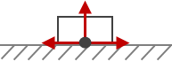
•Support with possible separation – nodes finite element mesh to which this boundary condition is applied are allowed to displacement tangentially to the tool plain surface and be separated from it in the direction normal to the tool plain surface:
•Load – determines the magnitude of the load acting on surface elements and its direction. The specified load is divided by the total area of the surface elements, the center of which falls within the boundary condition array, and the resulting specific force is applied to each of these elements
•Pressure – determines the amount of pressure acting on surface elements. A specified pressure is applied to each surface element whose center falls within the boundary condition domain. It is possible to set a constant pressure value or a pressure dependence over time:
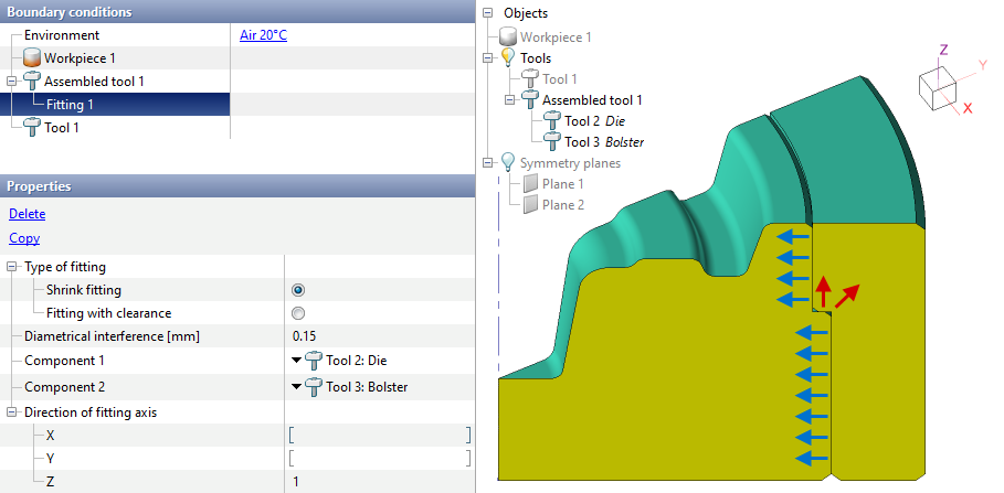
•Fittingcan only be specified for a assembled tool. This boundary condition allows us to take into account the change in the stress-strain state of a assembled tool caused by the interference or gap between the components of such a tool.
For the condition Fitting must be select Type of fitting - Fitting with clearance or Shrink fitting, then indicate the value of the gap or interference on the diameter.
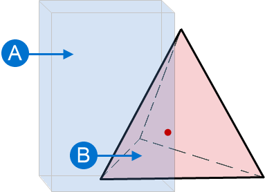
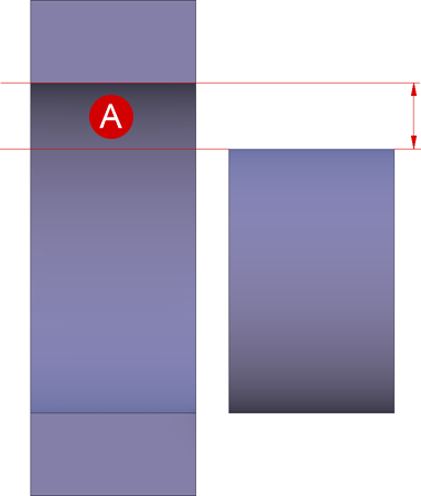
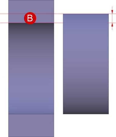
Condition Fitting applies to the contact surfaces of a assembled tool for which the normal vector is perpendicular to the specified fitting axis. The figure below shows an example of a task Fitting. The boundary condition applies only to those surfaces whose normal vectors are perpendicular to the specified fitting axis OZ (indicated by blue arrows), and do not apply to other surfaces (indicated by red arrows):
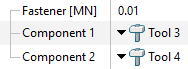
•Fastener – boundary condition can be imposed on the contact plain surface of the parts of a assembled tool. In a given domain, the part of the assembled tool will be in contact until the tensile load exceeds the specified fastener load:
|
|||||||||||||||||
See also: