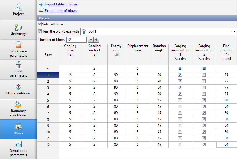
On the Blows tab the table of blows is presented. With the help of the table of blows , the amount of blows in one operation is set. For each blow it is possible to specify:
•cooling in air time ;
•cooling on tool time;
•Energy share of blow;
•Offset of the workpieces along the specified axes;
•Rotation angle of the workpieces around a given axes;
•Engagement of the forging manipulator;
•Final distance between tools.
Controlling the amount of blows
In the table of blows, each blow corresponds to a row with the corresponding blow number. By default there is just one blow:on the Blows tab
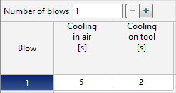
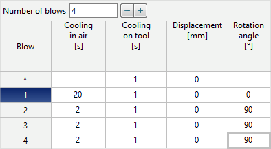
It is possible to control the amount of blows by directly entering the required number of blows manual, or help the buttons - and +.
|
Information |
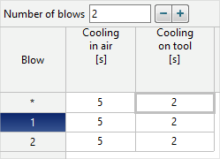
If there are more than one blows, a line with an index appears at the origin *. Specifying the value of any parameter in this line applies the same value to all blows. |
|
Blows parameters
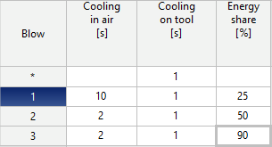
In the table of blows , each parameter corresponds to a column with the corresponding name. On the Blows tab there are always the further columns:Cooling in air and Cooling on tool. If certain condition are met, then advanced columns appear.
•Cooling in air - the parameter, designed to simulate the cooling of workpieces in the environment before blow within a specified time. It can be used to simulate cooling during transport from a heating furnace or cooling during the manipulation of the workpiece between blows.
The simulation of such cooling takes place at the zero step after the start of the simulation. Cooling is carried out in the environment without taking into account contact with the tool.
|
Information |
Even though the parameter is called Cooling in air, cooling will be carried out in accordance with the parameters of the fit by specified in the line Environment in the Boundary conditions tab. |
|
•Cooling on tool - parameter, designed to simulate the cooling of workpieces in tooling before blow within a specified time. Can be used to simulate cooling downtime before starting equipment or cooling down between blows.
The simulation of such cooling takes place at the zero step after the start of the simulation. Cooling is carried out in the environment, taking into account contact with the tool after contact.
•Energy share - parameter, designed to control blow energy.
|
Information |
A column becomes available if at least one tool has been given the equipment with the drive type Hammer or Screw drive. |
|
The initial blow energy will be the specified fraction of the total blow energy .
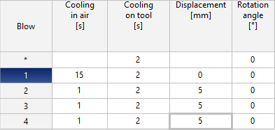
•Displacement - parameter, designed to automate the positioning of the workpieces.
|
Information |
The column becomes available ifaxis is specified to the workpieces. |
|
The Workpiece will move at the zero blow step after the start of the simulation. A positive value corresponds to the displacement in the direction of the axes (from the origin of the axes), a negative value - to the opposite direction (towards the origin of the axes).
|
Information |
If there are several workpieces in the simulation, then all workpieces will be moved, for which the axis is specified. The Distance over which the workpieces will move will be the same. |
|
•Rotation - parameter, designed to automate the positioning of the workpieces.
|
Information |
The column becomes available ifaxis is specified to the workpieces. |
|
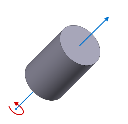
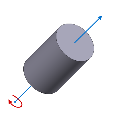
The Workpiece will be rotated at the zero blow step after starting the simulation. A positive value corresponds to a counterclockwise rotation around axis, a negative value corresponds to a clockwise rotation around axis.
|
|
|
|
|
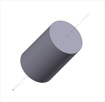
Workpiece and axis |
|
Positive value of the rotation angle Rotation counterclockwise around axis |
|
Negative value of rotation Clockwise Rotation around an axis |
|
Information |
If there are several workpieces in the simulation, then all workpieces will be moved, for which the axis is specified. The Angle at which the workpieces will rotate will be the same. |
|
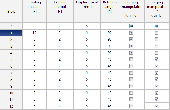
•Forging manipulator – parameters, designed to turn on and off forging manipulators. They can be used to simulate open die forging processes when the workpiece is held from one side to the other time the process.
|
Information |
The column becomes available if theaxis for the workpiece is specified and two or more additional boundary conditions domains of Forging manipulator. |
|
If there is a checkmark on the blow line in the column with the corresponding forging manipulator, then this forging manipulator will be active on the selected blow during the simulation. Otherwise, the forging manipulator will not hold the workpiece at the selected blow.
•Final distance - parameter, designed to control the stop condition Distance.
|
Information |
The column becomes available if on the Stop conditions tab for the condition Distance Individually for each blowis activated. For each such stop conditions Distance a separate column will be added. |
|
The blow simulation will be stopped when the distance between the tools is equal to the value specified for the given blow.
Additional parameters for simulation of multi-blow processes
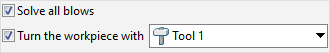
•The Solve all blows feature, allows you to start simulation of all blows in the table. With this feature, all blows will be calculated, regardless of the set stop conditions.
•Feature Rotate workpiece with..., allows you to rotate the selected tool to the same angle as the workpiece. The Tool will be rotated to bring it into contact at blow step zero after the simulation is started.
|
Information |
Feature Rotate workpiece with... becomes available if for the tool theAxis 1 is specified. The Tool will rotate around this axis. |
|
Work with the blows table in third-party applications
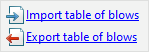
The blows table can be imported or exported with the files *.xlsx and *.xls. Export and import are carried out by commands located at the top of the Blows tab:
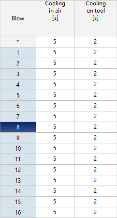
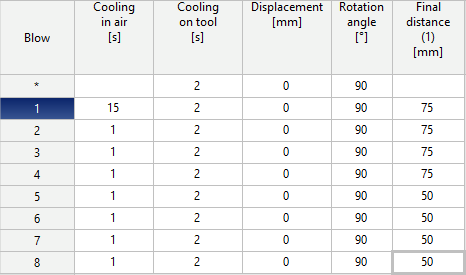
Below is what the blows table looks like when exported from QForm UK to Microsoft Excel:
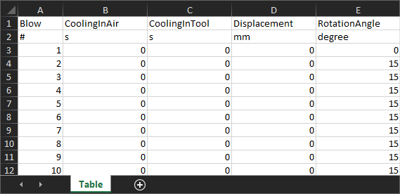
A similar structure should have a table prepared in Microsoft Excel for import into QForm UK.
Viewing simulation results of multi-blow processes simulation
Switching between blows can be done in two ways: helping the arrows Switching between blows on simulation control panels or by clicking on the blow number in the blows table . Switching is only possible for simulated blows. Depending on the blow state, the blow number in the table will have a different background - a gray background means that the blow is not simulated, a dark blue background means an active blow, a blue background means that the blow is simulated: