The standard equipment database supplied with the software contains examples of hammers, hydraulic, mechanical and screw presses.
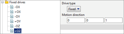
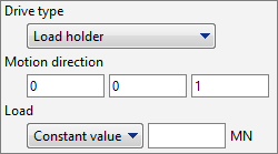
In QForm UK equipment is assigned separately for each tool. All fixed tools are assigned as Fixed drive. The direction of its action must coincide with the direction of putting into contact the selected tool and the workpiece. If putting into contact isn't defined, the choise of the direction doesn't matter. For convenience, the list of fixed drives is placed in a separate folder.
|
Information |
The drive direction also determines the forward and backward stops of the spring (spring loaded tool) as well as the axis along which the distance is determined for the stop condition Distance between tools. |
|
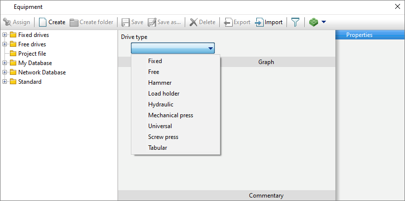
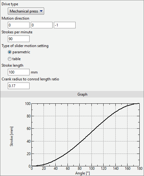
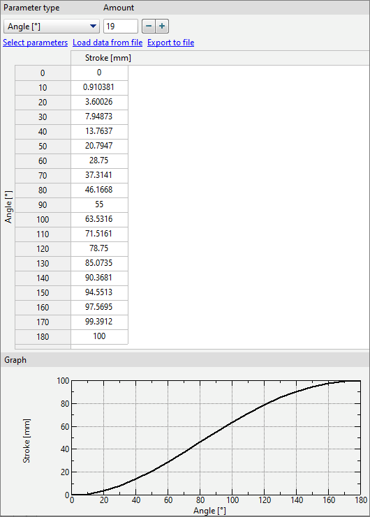
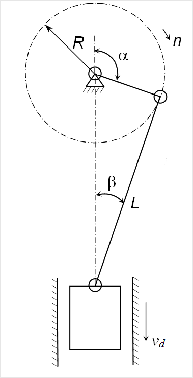
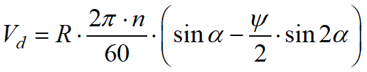
In the equipment database you can create the types of drives shown in the figure below:
Specified for stationary tools. In the column Motion direction the coordinates of the unit vector are indicated, which determines the direction of putting into contact the selected tool and the workpiece:
|
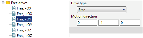
Set for free tools. In the column Motion direction the coordinates of the unit vector are indicated, which determines the direction of putting into contact the selected tool and the workpiece:
|
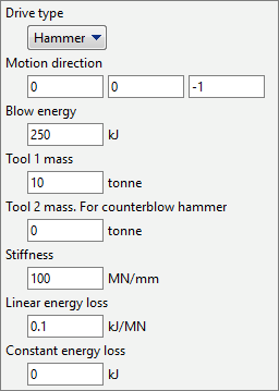
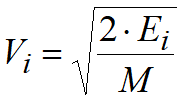
Motion direction is a unit vector that defines the direction of tool movement and the direction of automatic tool contact with the workpiece, if it is defined. Blow energy (kJ ) – hammer energy indicated in the passport. Tool 1 mass (tonne) – total mass of the hammer head and the top die. tool 2 mass (tonne) – if the hammer is not counterblow, then it should be set 0. If the hammer is counterblow, then the total mass of the lower head and the bottom die should be set. Stiffness (MN/mm) – characterizes the elastic losses of the hammer. It is recommended to set stiffness 100-150 MN/mm. Linear energy loss (kJ/MN) – coefficient characterizing losses into the fixed die. It is recommended to set it 0.1 kJ/MN. Constant energy loss (kJ) – friction losses, which are specified only for gravity hammers. It is recommended to set friction losses equal to 10% of the hammer energy.
|
||||||||||

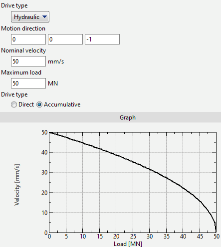
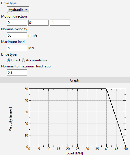
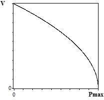
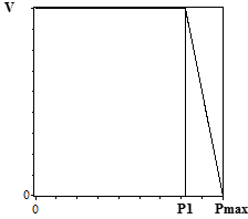
It is possible to specify two models of hydraulic press: with direct or accumulative drive. In principle, these two models differ in the dependence of the velocity on the current design force:
Motion directionis a unit vector that defines the direction of tool movement and the direction of automatic putting tool into contact with the workpiece, if defined. Nominal velocity – initial velocity of the tool, which, depending on the drive type, can change as the design force increases (as on the graphs above). Maximum load - when the condition P / Pmax> 0.9999 is fulfilled, the tool stops. Here P – design load, Pmax – maximum load. Nominal to maximum load ratio (k) – used only with direct drive. The tool velocity is constant until the design load P1= k·Pmax is reached, after which it starts to drop linearly. Usually k = 0.9. |
|
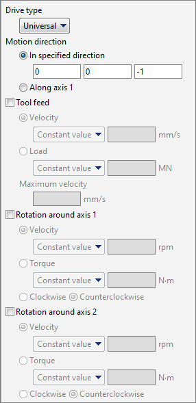
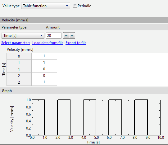
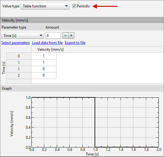
Motion direction is a unit vector that defines the direction of tool movement and the direction of automatic putting tool into contact with the workpiece, if defined. The direction of tool motion can be set as positive Axis 1 direction, which, in turn, can rotate around Axis 2. This feature can be used, for example, for modelling complex movement of strikers during rotary open die forging. Tool feed – can be specified in two ways: •velocity - a constant value or a table function (dependence of velocity on time); •load - a constant value or a table function (dependence of torque on time). Parameter Maximum velocity is used to correct the tool velocity: during simulation tool velocity cannot exceed the specified maximum velocity. Rotation around axis 1 - here you can set the parameters of tool rotation around axis 1, which is defined for this tool in the QShape geometry editor or directly inQForm UK in the Geometry tab. There are two options for specifying rotation: •velocity - a constant value or a table function (dependence of angular velocity on time); •torque - a constant value or a table function (dependence of torque on time). For example, if you set zero torque, the tool will rotate from friction with the workpiece without resistance. Rotation around axis 2 - here you can set the parameters of tool rotation around axis 2, which is defined for this tool in the QShape geometry editor or directly inQForm UK in the Geometry tab. There are two options for specifying rotation: There are two options for specifying rotation: •velocity - a constant value or a table function (dependence of angular velocity on time); •torque - a constant value or a table function (dependence of torque on time). If any universal drive parameter is described by a periodic table function, you can set the points of the repeating fragment of the table function and check the box Periodic:
|
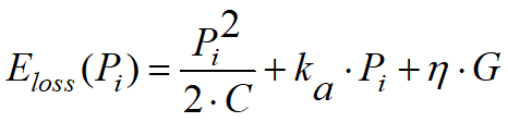
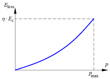
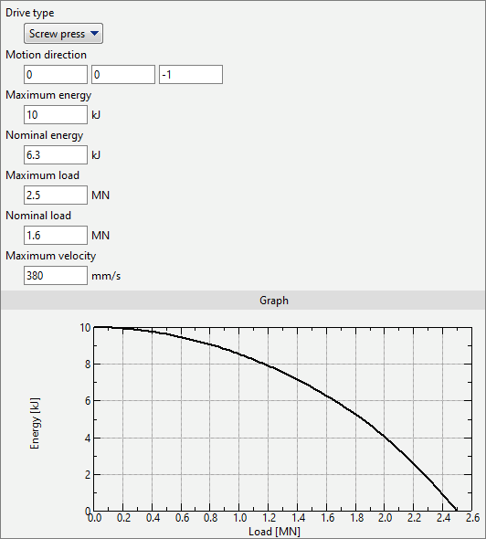
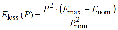
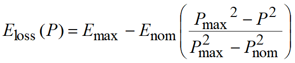
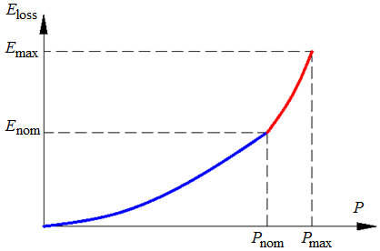
In QForm UK a model of a screw drive has been implemented, in which the dependence of the equipment loss energy on the current force on the slide is specified. This dependence takes into account only friction losses and elastic strain of parts of the screw drive, as well as losses associated with the inclusion of a safety friction clutch, if it is provided in the design of the press. This specification of the press model allows, by changing the value of the maximum and nominal energies and corresponding forces, to select a characteristic that most closely approximates a real screw drive. In addition, the screw press parameters specify the tool speed at the moment the tool touches the workpiece to determine the reduced mass of the falling parts.
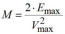
Motion direction is a unit vector that defines the direction of tool movement and the direction of automatic tool contact with the workpiece, if defined. Maximum energy (kJ) – maximum permissible blow energy specified in the press passport. Nominal energy (kJ) – blow energy permissible for work without activation of the safety mechanism. Maximum load (MN) - the maximum load that the press can develop. Nominal load (MN) – the load at which the safety mechanism begins to operate. Maximum velocity (mm/s) – the velocity of the slider immediately before the moment the tool touches the workpiece.
|
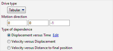
The tabular drive type is used to describe the translational motion of a tool using a tabular function:
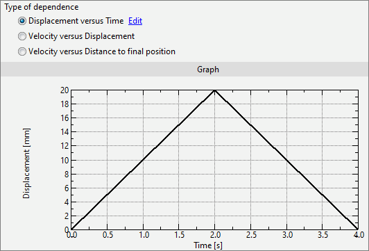
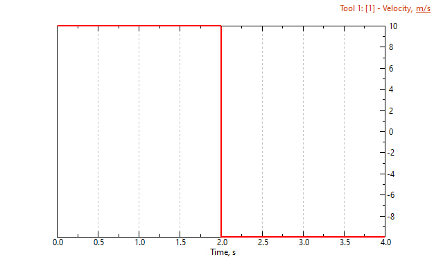
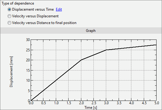
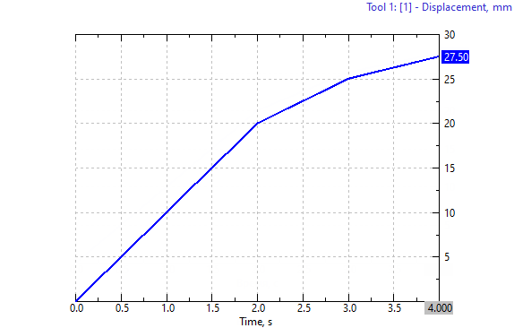
Motion direction - the direction in which the tool moves and the direction in which the tool is put into contact with the workpiece, if tool contact is defined in the Tool parameters. The following dependencies can be specified: Displacement on time – the dependence of the tool shift on time is specified, in this case the zero displacement value corresponds to the position of the tool in the first simulation record . The accuracy of tool shift in this case does not depend on the size of the simulation step and always corresponds to the graph defined by user:
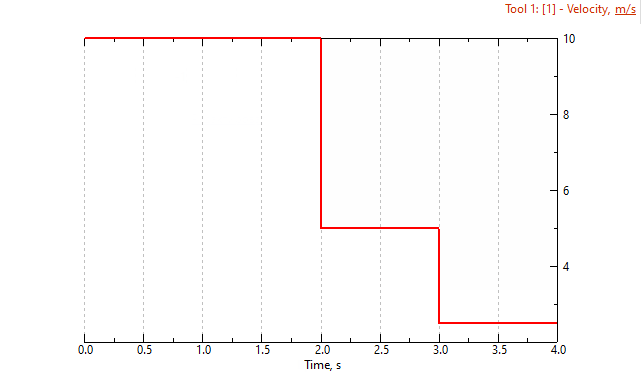
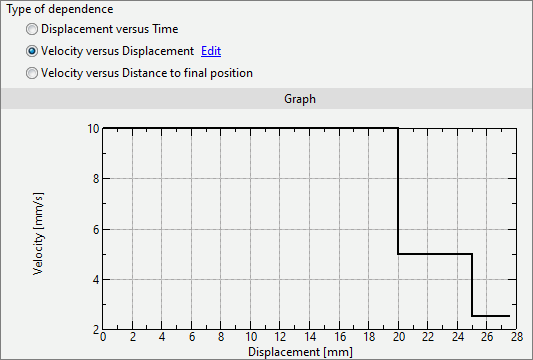
Velocity on displacement – defines the dependence of the tool velocity on the tool motion. In this case , the tool during the simulation process can only move in a user defined motion direction (only a positive velocity value). The zero displacement value corresponds to the position of the tool in the first simulation step. The accuracy of tool shift in this case depends on the size of the simulation step. With this method of specifying tool kinematics, no further tool movement is possible after the zero velocity point, if there is one on the graph.
Velocity on distance to final position defines the dependence of the tool velocity on the distance left to be covered by the tool before its end position. In this case , the tool during the simulation process can only move in a user defined motion direction (only a positive velocity value). The Maximum value of the distance to the final position corresponds to the position of the tool in the first simulation step. The accuracy of tool shift in this case does not depend on the size of the simulation step. With this method of specifying tool kinematics, no further tool movement is possible after the zero velocity point, if there is one on the graph. Only Distance can be used as a stop condition.
|
|||||||||||||||||||
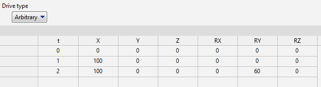
Arbitrary drive type is intended to describe complex arbitrary movement of the tool. Complex movement of the tool is achieved by setting several positions of the tool relative to the origin, differing in time. Field for specifying tool positions:
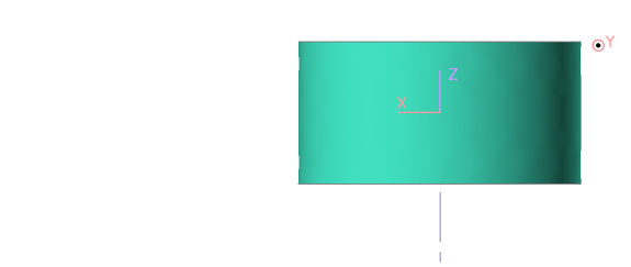
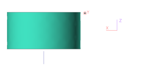
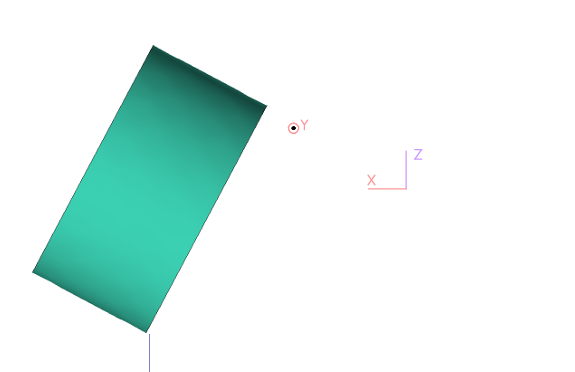
Where t — time, in seconds; X, Y, Z — coordinates of the tool along the X, Y and Z axes, respectively, in millimeters; RX, RY, RZ — angles of rotation of the tool around the X, Y and Z axes, respectively, in degrees Reference positions of the instrument according to the data from the table above:
Between these positions, smooth interpolation occurs, creating continuous movement of the tool. When using a arbitrary drive, the following features should be taken into account: •In order to put a tool, specified in an arbitrary way, into contact with a workpiece, it is necessary to specify an axis for the tool. The positive direction of putting into contact with the workpiece will be determined by the positive direction of the given tool axis; •The initial position of the tool (or the position of the tool after putting it into contact with the workpiece) always has a zero angle of rotation relative to all axes, regardless of the specified values for t equal to 0 seconds; •The force graph for an arbitrary tool displays the change in force in the normal direction from the first to the final position of the tool. |
See also: