In the tab Tool parameters the material, temperature, lubricant, type of heat transfer to workpiece and other additional parameters of the tool are assigned:
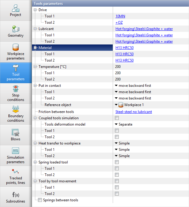
The tab displays the following sections:
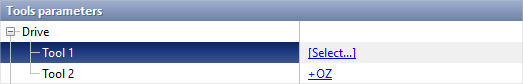
In the section Drive kinematic and dynamics parameters are set for each tool. To assign these parameters, you have to click [Select...]next to the corresponding tool, in the equipment database window that opens, select the drive and assign it by double clicking the mouse or using the button Assign:
See also: |
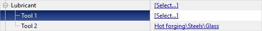
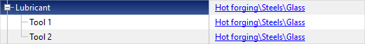
In the section Lubricant the parameters of friction and heat transfer between workpiece and the tool are set. To assign these parameters, you have to click [Select...]next to the corresponding tool, in the database window that opens, select a lubricant and assign it by double clicking the mouse or button Assign:
If you press [Select...] next to the section Lubricant, then the lubricant will be assigned to all tools at once:
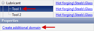
To assign the friction conditions and heat transfer between workpiece and the tool for a local domain, you need to click on the line with the desired tool and in the window Properties press Create an additional array:
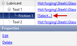
You can create one or more frictionlocal domains and heat transfer between workpiece and the selected tool. After specifying the domain in the field Lubricant an additional numbered block will appear in which you need to specify lubricants parameters:
See also: |
||||
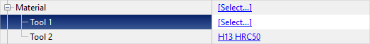
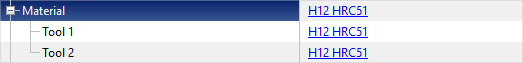
In the section Material the parameters of the tool material are set. To assign these parameters, you have to click [Select...]next to the corresponding tool, in the database window that opens, select a material and assign it by double clicking the mouse or using the button Assign:
If you press [Select...] next to the section Material, then the material will be assigned to all tools at once:
See also: |
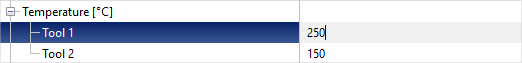
The tools temperature is set here. The Temperature can be entered separately for each tool:
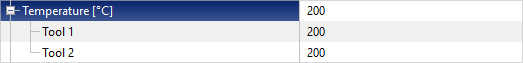
If you enter a value in the section Temperature, then it will be specified immediately for all tools:
|
||||
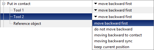
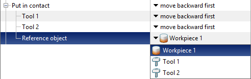
Here you set the method of bringing the tool into contact with the workpiece at the origin of the simulation:
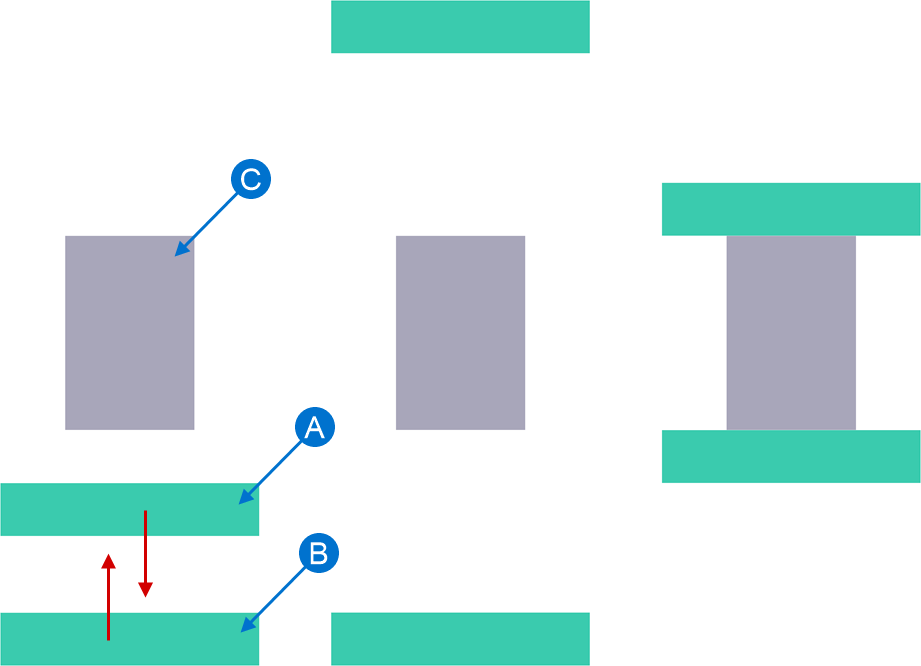
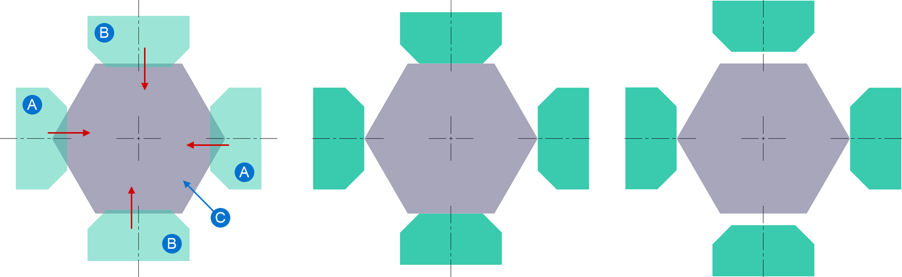
Here, the reference object is set, the object to which the contact will be made. During contact, the reference object always remains stationary, while other objects move. The following are examples with a reference object – a workpiece. There are four contact cases: Move backward first,Do not move backward, Moving backward to contact,Moving backward sync,Keep current position. Move backward first – if the tool crosses the workpiece, or the workpiece is in the opposite direction relative to the motion direction of the drive of tool, then the tool is retracted against the motion direction of the drive behind the workpiece and then move into the contact with it. The figure below shows the principle of bringing into contact "move backward first", the arrows indicate the motion direction of the drive of each tool:
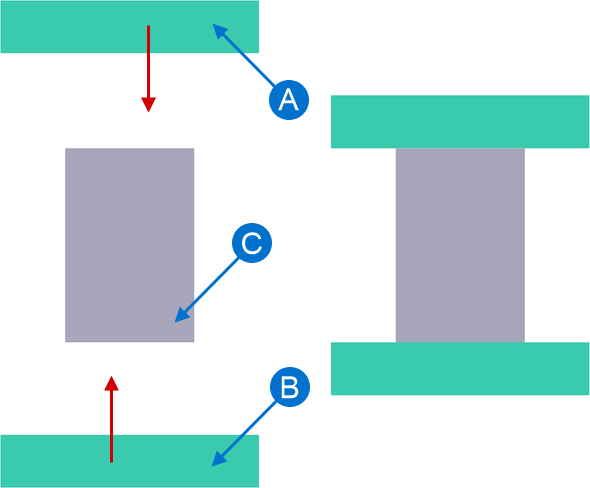
Do not move backward - the tools are put into contact with the workpiece in the motion direction of the user defined drive do not move backward. The figure below shows the principle of bringing into contact “do not move backward”, the arrows indicate the motion direction of the drive of each tool:
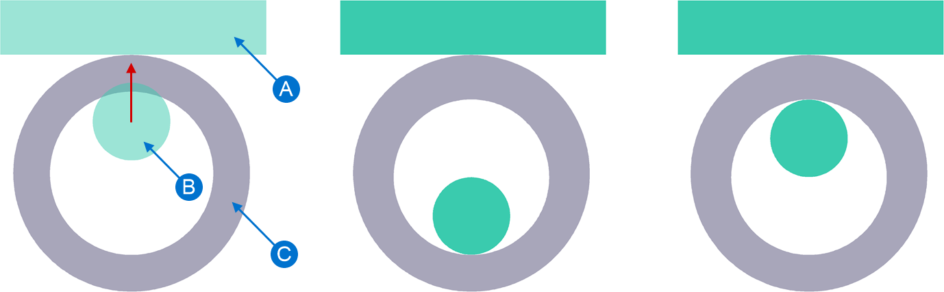
With moving backward to contact – used, for example, in processes such as mandrel rolling. If the workpiece has a hole and the tool is in this hole or intersects with it, then when put into contact, the tool is first retracted against the motion direction of the drive until it contacts the inner plain surface of the workpiece and then put into contact with the plain surface of the workpieces in the motion direction of the drive. The figure below shows the principle of bringing into contact with "moving backward to contact", the arrow shows the motion direction of the drive of tool:
Withmoving backward sync – used, for example, to simulation processes using forging machines. It is typical for such equipment that the drives of different tools are mechanically interconnected. This means that the tools move synchronously, that is, they move forward and back the same distance. In this case, the tools are moving back the same distance and approach the tool until at least one of the tools is brought into contact. The figure below shows a comparison of contact information Move backward first and Moving backward sync, the arrow shows the motion direction of the drive of tool:
Keep current position – before the simulation start, the tools maintain their original position and are not brought into contact with the workpiece. |
|||||||||||||||||||||||||||||||||
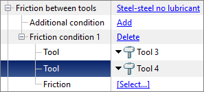
Here are specified parameters of friction and heat transfer between tools. Friction between tools have to be assign if an assembled tool is specified in the simulation. The default model is set to Steel-steel no lubricant. To view the parameters of model, click on Steel-steel no lubricant. Inthe database window that opens, you can also create another one and select a lubricant and assign it by double clicking the mouse or button Assign. If there are more than two tools, it becomes possible to set the advanced friction conditions between tools in cases where the condition for certain tools are different.
See also: |
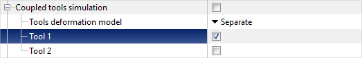
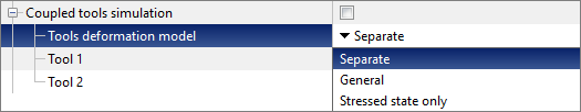
It is used when it is necessary to take into account elasto-plastic deformation of the tool during simulation of workpiece deformation. On some simulation records determined by the applications algorithm, stresses and elastic deformations in the tool are simulated. To take into account coupled deformation, you need to check the boxes opposite to the corresponding tools:
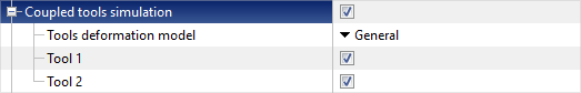
If you check the box next to Coupled tools simulation, then taking into account coupled deformation will be activated for all tools:
In the software you can select one of two models for simulation of coupled deformation: Separate or General:
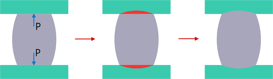
When using simplified Separate model, the simulation of coupled deformation at each simulation step consists of three stages: first, the workpiece is deformed with a rigid tool, at the end of the calculation step, the load with which the workpiece acts on the tool are determined, the elastic-plastic deflection of the tool is determined, after which the software compensates for the volume of the workpieces in the places where the tool deflects:
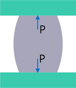
Using General the workpiece and tools are deformed during the simulation process as a single system. In this case, the simulation duration increases significantly:
When using the model Stressed state only simulation are carried out without changing the shape of the tool. This feature allows the simulation of the stressed state of the tool, if the tool deformation can be neglected. This model allows you to take advantage of the benefits of coupled simulation without significantly increasing the duration of the simulation.
See also: |
||||||||

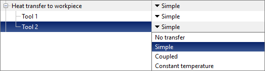
There are four possible cases for heat transfer between tool and the workpiece: No transfer, Simple, Coupled, Constant temperature:
No transfer – in this case, the condition of heat transfer on the surface of the workpiece in contact with the tool corresponds to heat exchange with the environment. That is, if, for example, the environment - Air, then in contact with the tool the workpiece is cooled as if in the air. Simple – a simplified joint thermal task is solved in the contact with the tool. Such heat transfer is realized by special surface thermal elements on the tool, invisible to the user. In this case, the change in tool temperature is calculated only on those tool surfaces where contact with the workpiece occurred. Coupled – the temperature is calculated in the all volume of the tool. Heat transfer to workpiece, the environment and contacting tools is taken into account. Constant temperature – in this case, the tool temperature is not calculated and remains constant. Always specified by default Simple heat transfer to workpiece, this heat exchange case is recommended for the most of cases. See also: Features of the numerical implementation of heat transfer between the workpiece and the tool |
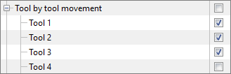
By default, in QForm UK tools can pass through each other freely. Feature tool by tool movement includes interaction between tools.
See also: |
||||||||
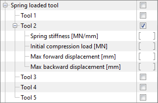
Feature Spring loaded tool is designed to use with kinematic drives. That is, with drives whose velocity is clearly defined. For example, with a mechanical or fixed drive. In this case, the drive is a virtual object and is not shown in the simulation environment.
Common activation Spring loaded tool activates the feature for all tools. Activation of individual tools is also available. When activated, sections Spring stiffness [MN/mm], Initial compression load [MN], Forward stop [mm] and Back stop [mm] become available for which you need to enter the appropriate value:
Spring stiffness [MN/mm] and Initial compression load [MN] are required parameters, and Forward stop [mm] and Back stop [mm] - advanced.
The speed of movement of a spring-loaded tool during unloading (the speed of unloading a compressed spring) is limited by the inertial properties of the tool itself. That is, when calculating the acceleration with which a spring-loaded tool moves during unloading, the mass of this tool is taken into account. Estimation of achievement of stop conditions Distance between tools and Tool stroke will be carried out by drive movement, not the tool. For example, a stop condition is specified Distance between tools, equal S. One of the tools is spring-loaded; in the process of deformation, the spring compressed by an amount equal to s. Thus, the process will stop when the distance between the tools is equal S+s. See also: |
||||||||||||
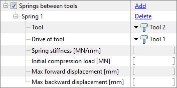
Feature Springs between tools designed for use with kinematic drives. That is, with drives whose velocity is clearly defined. For example, with a mechanical or fixed drive. This feature works similarly to the feature Spring loaded tool, however, unlike the virtual drive, for the feature Springs between tools it will be necessary to assign a driven tool in addition to the spring loaded tool.
Common activation Springs between tools activates the feature and allows you to specify a pair of spring-loaded tools. First you need to select a spring loaded tool. The spring loaded tool selection is available only to tools for which have Free drive type Next you need to select a driving tool. Any tools with any drive type is available for selection of driving tool, however this option is intended to use with kinematic drives only.
Spring stiffness [MN/mm] and Initial compression load [MN] are required parameters, and Forward stop [mm] and Back stop [mm] - advanced.
The motion direction specified for the drives of the selected tools is of great value. Feature Springs between tools is intended for such computations where the drives of both tools are directed along the same axes, that is, the unit direction vectors of the drives of the selected tools are collinear.
If the direction of the drives of the spring loaded tool and the driving tool are in opposite directions, then when these tools approach each other and the spring is compressed, the limitation will be the parameter Forward stop [mm]. And vice versa - if the unit direction vectors of the drives of the spring loaded tool and the driven tool are co-directed, then when these tools approach each other and the spring is compressed, the limitation will be the parameter Back stop [mm]. If the direction of the spring loaded tool and the driving tool are non-collinear, then the simulation of the kinematics of the spring loaded tool motion and the evaluation of the displacement limits may be calculated differently than expected. When a limit is reached, the kinematic of the spring loaded tool will match the kinematic of the driving tool as long as the force on the spring loaded tool is sufficient to maintain the limit.
See also: |
||||||||||||||||