An example of simulation is considered coupled deformation task, which involves taking into account the elastic deformations of the tool time the simulation of the shape change of the workpieces.
Operation 1 |
Operation 2 |
|
|
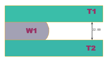
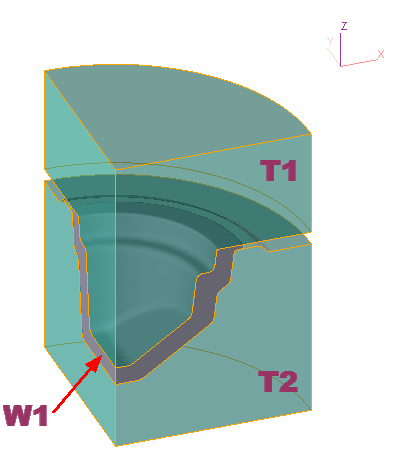
The task consists of two operations: upsetting and final forging. To simulate the first operation, a 2D axisymmetric task is used. To simulation the second operation, a 3D task with two symmetry planes is used. In both operations, the workpiece deformation is considered together with the simulation of the elastic deformations of the tools, therefore, boundary conditions must be specified for all tools (for example, rigid fixing).
Initial data
Operation 1 |
||
|---|---|---|
Operation |
Operation type |
General forming |
Additional parameters |
With thermal process |
|
Problem type |
2D axisymmetric |
|
Geometry |
Load from file |
cover_op1.dxf |
Workpiece parameters |
Material |
Steels\Carbon steels\С22(1-0402) |
Temperature |
1200˚С |
|
Tool parameters |
Drive |
Tool 1 - Mechanical press 25 MN Tool 2 - Fixed drive +OZ |
Lubricant |
Tool 1, 2 - Graphite-water (Hot forging/Steels/Graphite + Water) |
|
Material |
Tool 1, 2 - L6HRC42 |
|
Temperature |
Tool 1, 2 - 150˚С |
|
Coupled tools simulation |
Yes; Tools deformation model - Separate |
|
Heat transfer to workpiece |
Simple |
|
Stop conditions |
Distance |
22 mm between Tool 1 and Tool 2 |
Boundary conditions |
Environment |
Air 20˚C |
Blows |
Number of blows |
1 |
Cooling in air |
5 s |
|
Cooling on tool |
2 s |
|
Simulation parameters |
|
Default |
Operation 2 |
||
Operation |
Operation type |
General forming |
Additional parameters |
With thermal process |
|
Problem type |
3D |
|
Geometry |
Load from file |
cover_op2.shl |
Workpiece parameters |
Material |
Inherited from previous operation |
Temperature |
Inherited from a previous operation |
|
Tool parameters |
Drive |
Tool 1 - Mechanical press 25 MN Tool 2 - Fixed drive +OZ |
Lubricant |
Tool 1, 2 - Graphite-water (Hot forging/Steels/Graphite + Water) |
|
Material |
Tool 1, 2 - L6HRC42 |
|
Temperature |
Tool 1, 2 - 150˚С |
|
Coupled tools simulation |
Yes; Tools deformation model - Separate |
|
Heat transfer to workpiece |
Simple |
|
Stop conditions |
Distance |
2 mm between Tool 1 and Tool 2 |
Boundary conditions |
Environment |
Air 20˚С |
Blows |
Blows |
1 |
Cooling in air |
0 s |
|
Cooling on tool |
1 s |
|
Simulation parameters |
|
Default |
1.Click Create new process

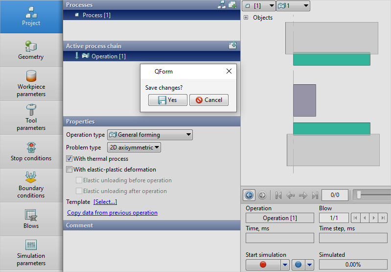
2.In the Operation tab select Operation type - General forming, With thermal process, Problem type - 2D axisymmetric. Click Forward

3.In the Geometry tab click Load from file and specify the path to the geometry file C:\QForm UK\12.0.1\geometry\cover\cover_op1.dxf. The uploaded geometry will appear on screen. Click Forward

4.In the Workpiece parameters tab you need to set the material and workpiece temperature. Click opposite Material [Select...]

In the database window that opens, select the material Steels\Carbon steels\C22 (1-0402) and double click on it, after that the material will appear in the Workpiece parameters tab

Set the workpiece temperature to 1200˚C. Click Forward
5.In the tab Tool parameters the drive type, temperature and lubricant must be select for each tool. To be noted that in this example Tool 1 - upper tool, and Tool 2 - bottom tool. Opposite Drive-Tool 1 click [Select...], and the equipment database window will be opened. Choose equipment Standard\Mechanical press\25MN and double click on it, after that the selected drive will appear opposite Drive-Tool 1

Tool 2 - fixed and it acts in the direction of the axes OZ. Next to Drive-Tool 2 click [Select...], in the equipment database window, select Fixed drives\+OZ and double click on it, the selected drive will appear in front of Drive-Tool 2

Opposite Lubricant click [Select...] and by double click set lubricant Hot forging/Steels/Graphite + Water. Lubricant will appear immediately for all tools.
Next to Material click [Select...] and double click to set the material L6HRC42. The Material will appear immediately for all tools. Opposite Temperature set tool temperature 150°C.
In order to take into account the elastic deformation of the tools during the simulation, check the box in front of Coupled tools simulation. Click Forward

6.In the Stop conditions tab you should set final distance between the tools. Click Distance. After that, specify the value of the final distance (22 mm). Click Forward

7.In the Boundary conditions tab, it is necessary to assign the tools constraints. Highlight Tool 1, and a list of boundary conditions will appear below. Click Rigid fixing

Next, you need to select the domain shape. Click Rectangular

Enter the domain size along the OX and OZ axes , then help the button![]() go into positioning mode and move the created brick array so that it intersects the dockable part of the tool. Click OK
go into positioning mode and move the created brick array so that it intersects the dockable part of the tool. Click OK

Similarly, set the rigid fixing for Tool 2. After assigning all necessary boundary conditions clickForward
8.In the Blows tab set the cooling in air and in the tool. Click Forward

9.In the Simulation parameters tab all remains unchanged. Click OK.
10.Click on the button Simulation![]() , and the program will ask to save the project. Give the project a name and click yes. The simulation will start
, and the program will ask to save the project. Give the project a name and click yes. The simulation will start
11.After the operation has been calculated, open the tab Project and click on the button Add an operation to the chain

12.In the Operation tab select Operation type - General forming, With thermal process, Problem type - 3D. Click Forward

13.In the Geometry tab click Load from file and specify the path to the geometry file C:\QForm UK\12.0.1\geometry\cover\cover_op2.shl. The loaded geometry will appear on screen. Click Forward

14.In the Workpiece parameters tab all remains unchanged: the workpiece and its temperature are inherited from the first operation. Click Forward.
15.In the Tool parameters tab set all as for the first operation. Click Forward.
16.In the tab Stop conditions it is should be set the final distance between the tools. Click Distance. After that, specify the value of the final distance (2 mm). Click Forward

17.In the tab Boundary conditions it is should be set the fixing for the tools. Select Tool 1, and a list of boundary conditions will appear below. Click Rigid fixing
Select the domain shape. Click Cylinder

Enter the dimensions of the cylinder domain manually, after that, click the button![]() to switch to positioning mode and move the created domain so that it intersects the part of the tool to be fixed. Click OK
to switch to positioning mode and move the created domain so that it intersects the part of the tool to be fixed. Click OK

Similarly, set the rigid fixing for Tool 2. After assigning all necessary boundary conditions click Forward.
18.In the Blows tab set the cooling on tool. Click Forward.
19.In the tab Simulation parameters all remains unchanged. Click OK.
20.Save the project and click on the button Simulation![]()