Cold forging produces high-precision parts with a surface quality that does not require additional machining. In this case, there are limitations associated with higher deformation forces and tool life.
Technology simulation allows expanding the range of products manufactured on existing equipment, as well as reasonably assessing the feasibility of purchasing new cold heading machines and other types of machines, based on their optimal use.
The following is an example of simulation cold forging bolt.
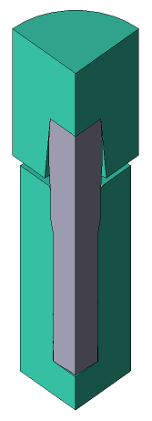
Operation 1 |
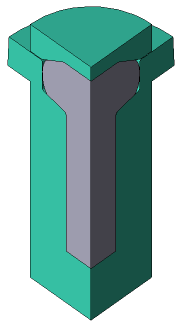
Operation 2 |
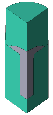
Operation 3 |
|
|
|
Initial data
Operation 1 |
||
Operation |
Operation type |
General forming |
Additional parameters |
With thermal process |
|
Problem type |
3D |
|
Geometry |
Load from file |
bolt_3D_op1.shl |
Workpiece parameters |
Material |
Steels\Carbon steels\C22 (1-0402) cold |
Temperature |
20 ˚С |
|
Tool parameters |
Drive |
Tool 1 - Mechanical press 6.3 MN Tool 2 - Fixed drive +OZ |
Lubricant |
Tool 1, 2 - Without lubricants (Cold forging/Steels/Unlubricated) |
|
Material |
Tool 1, 2 - H13HRC50 |
|
Temperature |
Tool 1, 2 - 20 ˚С |
|
Coupled deformation |
Not |
|
Heat transfer to workpiece |
Simple |
|
Stop conditions |
Distance |
1.5 mm between Tool 1 and Tool 2 |
Boundary conditions |
Environment |
Air 20 ˚С |
Blows |
Number of blows |
1 |
Cooling in air |
0 s |
|
Cooling on tool |
0 s |
|
Simulation parameters |
|
Default |
Operation 2 |
||
Operation |
Operation type |
General forming |
Additional parameters |
With thermal process |
|
Problem type |
3D |
|
Geometry |
Load from file |
bolt_3D_op2.shl |
Workpiece parameters |
Material |
Inherited from previous operation |
Temperature |
Inherited from previous operation |
|
Tool parameters |
Drive |
Tool 1 - Mechanical press 6.3 MN Tool 2 - Fixed drive +OZ |
Lubricant |
Tool 1, 2 - Without lubricants (Cold forging/Steels/Unlubricated) |
|
Material |
Tool 1, 2 - H13HRC50 |
|
Temperature |
Tool 1, 2 - 20 ˚С |
|
Coupled deformation |
Not |
|
Heat transfer to workpiece |
Simple |
|
Stop conditions |
Distance |
0.2 mm between Tool 1 and Tool 2 |
Boundary conditions |
Environment |
Air 20 ˚С |
Blows |
Number of blows |
1 |
Cooling in air |
0.3 s |
|
Cooling on tool |
0.3 s |
|
Simulation parameters |
|
Default |
Operation 3 |
||
Operation |
Operation type |
General forming |
Additional parameters |
With thermal process |
|
Problem type |
3D |
|
Geometry |
Load from file |
bolt_3D_op3.shl |
Workpiece parameters |
Material |
Inherited from previous operation |
Temperature |
Inherited from previous operation |
|
Tool parameters |
Drive |
Tool 1 - Mechanical press 6.3 MN Tool 2 - Fixed drive +OZ |
Lubricant |
Tool 1, 2 - Without lubricants (Cold forging/Steels/Unlubricated) |
|
Material |
Tool 1, 2 - X12MF (GOST) |
|
Temperature |
Tool 1, 2 - 20 ˚С |
|
Coupled deformation |
No |
|
Heat transfer to workpiece |
Simple |
|
Stop conditions |
Distance |
mm between Tool 1 and Tool 2 |
Boundary conditions |
Environment |
Air 20 ˚С |
Blows |
Number of blows |
1 |
Cooling in air |
0.3 s |
|
Cooling on tool |
0.3 s |
|
Simulation parameters |
|
Default |
1.Click Create a new process.
2.In the Operation tab select Operation type - General forming, With thermal process, Problem type - 3D. Click Forward.
3.In the tab Geometry click Load from file and specify the path to the geometry file C:\QForm UK\12.0.1\geometry\bolt_3D\bolt_3D_op1.shl.
The loaded geometry will appear on screen. ClickForward
4.In the Workpiece parameters tab you need to set the material and workpiece temperature. Click opposite Material[Select...].
In the database window that opens, select the material Steels\Carbon steels\C22 (1-0402) cold and double click on it, after which the material will appear in the tabWorkpiece parameters.
Set the workpiece temperature to 20˚C. Click Forward
5.In the tab Tool parameters the drive type, temperature and lubricant must be select for each tool. Opposite Drive- Tool 1 click [Select...] the database window will open. Choose equipment Standard\Mechanical press\6.3MN and click on it twice, after that the selected drive will appear opposite Drive- Tool 1. Tool 2 - fixed, and it works in the direction of the OZ axes . Opposite Drive- Tool 2 click [Select...], in the equipment database window, select Fixed drives\+OZ and double click on it, the selected drive will appear opposite Drive- Tool 2.
Further opposite Lubricant click [Select...] and double click to set the lubricant Cold forging/Steels/Unlubricated (without lubricants). Lubricant will appear at point Lubricant right opposite to all the tools.
Opposite Material click [Select...] and double click to set the material H13HRC50. Click Forward

6.In the tab Stop conditions it is necessary to set the final distance between the tools.
Click Distance, after that specify the value of the final distance - 1.5 mm. Click Forward
7.In the Boundary conditions tab all remains unchanged. Click Forward
8.In the tab Blows all remains unchanged. Click Forward
9.In the Simulation parameters tab all remains unchanged. Click Done
10.Click on the button Simulation![]() , and the program will ask to save the project. Give the project a name and click yes. After that, the simulation of the first operation will begin.
, and the program will ask to save the project. Give the project a name and click yes. After that, the simulation of the first operation will begin.
11.When simulation of the operation is finished, open the Project tab and press Add an operation to a chain

12.In the tab Operation select Operation type - General forming, With thermal process, Problem type - 3D. Click Forward.
13.In the tab Geometry click Load from file and specify the path to the geometry file C:\QForm UK\12.0.1\geometry\bolt_3D\bolt_3D_op2.shl.
The uploaded geometry will appear on screen. Click Forward
14.In the Workpiece parameters tab all remains unchanged. Material, Temperature and Accumulated degree of general forminginherited from the previous operation. Click Forward
15.In the Tool parameters tab set all as for the first operation. Click Forward
16.In the tab Stop conditions it is necessary to set the final distance between the tools.
Click Distance, after that specify the value of the final distance - 0.2 mm. Click Forward
17.In the tab Boundary conditions all remains unchanged. Click Forward
18.In the tab Blows ask cooling time in cooling in air0.3With) and in tool (0.3With). Click Forward
19.In the tab Simulation parameters all remains unchanged. Click OK
20.Click on the button Simulation![]() , and the software will offer to save the project. Save the project and after that the simulation of the second operation will start.
, and the software will offer to save the project. Save the project and after that the simulation of the second operation will start.
21.When the operation is calculated, open the tab Project and press Add an operation to a chain.

22.In the tab Operation select Operation type - General forming, With thermal process, Problem type - 3D. Click Forward.
23.In the tab Geometry click Load from file and specify the path to the geometry file C:\QForm UK\12.0.1\geometry\bolt_3D\bolt_3D_op3.shl.
The loaded geometry will appear on screen. Click Forward
24. In the tab Workpiece parameters all remains unchanged. Material, Temperature and Accumulated strain inherited from the previous operation. Click Forward
25. In the tab Tool parameters set all as for the previous operation. Click Forward
26. In the tab Stop conditions it is necessary to set the final distance between the tools.
Click Distance, after that specify the value of the final distance - 0.18 mm. Click Forward
27. In the tab Boundary conditions all remains unchanged. Click Forward
28. In the tab Blows set the cooling in air (0.3 s) and in the tool (0.3 s). Click Forward
29. In the tab Simulation parameters all remains unchanged. Click OK
30. Click on the button Simulation![]() , and the software will offer to save the project. Save the project and after that the simulation of the third operation will start.
, and the software will offer to save the project. Save the project and after that the simulation of the third operation will start.
