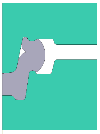
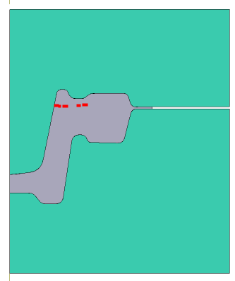
In QForm UK laps prediction algorithms were completely redeveloped, which made it possible to significantly increase the reliability of the application. The appearance of a lap during the simulation process is identified by red dots on the workpiece , which show the contact of the workpieces surface itself. Below is the process of hot forging a flange from a steel cylinder workpieces.
|
|
|

Initial data
Operation 1 |
||
Operation |
Operation type |
General forming |
Problem type |
2D axisymmetric |
|
Additional parameters |
With thermal process |
|
Geometry |
Load from file |
lap.dxf |
Workpiece parameters |
Material |
Steels\Carbon steels\C10 (1-0301) |
Temperature |
1200˚С |
|
Tool parameters |
Drive |
Tool 1 - Mechanical press 10 MN Tool 2 - Fixed drive +OZ |
Lubricant |
Tool 1, 2 - Graphite and water (Hot forging/Steels/Graphite + Water) |
|
Material |
Tool 1, 2 - H13 HRC50 |
|
Temperature |
Tool 1, 2 - 200˚С |
|
Coupled tools simulation |
Not |
|
Heat transfer to workpiece |
Simple |
|
Stop conditions |
Distance |
1 mm between Tool 1 And Tool 2 |
Boundary conditions |
Environment |
Air 20˚C |
Blows |
Number of blows |
1 |
Cooling in air |
4 s |
|
Cooling on tool |
2 s |
|
Simulation parameters |
|
Default |
1.Click Create new process
2.In the tab Operation select Operation type - General forming, Problem type - 2D axisymmetric. Click Forward
3.In the tab Geometry click Load from file and specify the path to the geometry file C:\QForm UK\12.0.1\geometry\laps_prediction\lap.dxf. The uploaded geometry will appear on screen. ClickForward

4.In the tab Workpiece parameters you need to set the material and temperature of workpiece. Click opposite Material[Select...]
In the database window that opens, select the material Steels\Carbon steels\C10 (1-0301) and double click on it, after that the material will appear in the tab Workpiece parameters
Set workpiece temperature 1200˚С. Click Forward
5.In the tab Tool parameters drive type, temperature and lubricant should be select for each tool. Opposite Drive-Tool 1 click [Select...] the database window will open. Choose equipment Standard\Mechanical press\10MN and double click on it, after that the selected drive will appear opposite Drive-Tool 1. Tool 2 - fixed, and it acts in the direction of the OZ axes. Opposite Drive-Tool 2 click [Select...], in the equipment database window, select Fixed drives\+OZ and double click on it,the selected drive will appear opposite Drive-Tool 2.
Further opposite Lubricant click [Select...] and double click to set the lubricant Hot forging/Steels/Graphite + water. Lubricant will appear at point Lubricant right opposite to all the tools.
Opposite Material click [Select...] and double click to set the material H13 HRC50. It is also necessary to assign the temperature Tools 1, 2 - 200 degrees. Click Forward

6.In the Stop conditions tab you should set final distance between the tools. Click Distance. After this, specify the value of the final distance 1 mm. Click Forward
7.In the Boundary conditions tab all remains unchanged. Click Forward.
8.In the tab Blows you need to set cooling time in air (4 s) and in the tool (2 s). Click Forward
9.In the Simulation parameters tab all remains unchanged. Click OK
10.Click on the button Simulation![]() , and the program will ask to save the project. Set the project name and click Save. The simulation will start after that.
, and the program will ask to save the project. Set the project name and click Save. The simulation will start after that.
