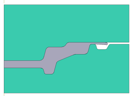
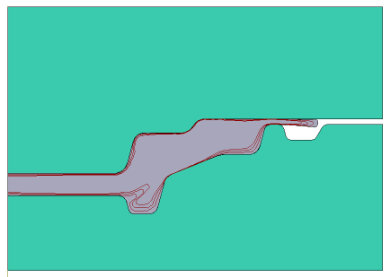
In addition to vertical and horizontal Lagrangian lines, the software has the ability to analyze undersurface flow lines. They are set along the plain surface of the workpieces. Line are closed contours that follow the outline of a surface contour. They are deformed along with the material particles of the workpieces. The main purpose of undersurface flow lines is to identify surface defects in workpieces during forging. Such defects include perforating and shrinkage depression.
In QForm UK It is possible to trace lines throughout the operation. To specify undersurface flow lines, you must activate the first simulation record , and in the tabTracked points, linepressCreate undersurface flow lines. Below is an example of hot bulk forging:
|
|
|
Initial data
Operation 1 |
||
Operation |
Operation type |
General forming |
Problem type |
2D axisymmetric |
|
Additional parameters |
With thermal process |
|
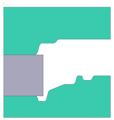
Geometry |
Load from file |
defect.dxf |
Workpiece parameters |
Material |
Steels\Carbon steels\C10 (1-0301) |
Temperature |
1200˚С |
|
Tool parameters |
Drive |
Tool 1 - Mechanical press 6.3 MH Tool 2 - Fixed drive +OZ |
Lubricant |
Tool 1, 2 - Graphite and water (Hot forging/Steels/Graphite + Water) |
|
Material |
Tool 1, 2 - H13 HRC50 |
|
Temperature |
Tool 1, 2 - 200˚С |
|
Coupled tools simulation |
Not |
|
Heat transfer to workpiece |
Simple |
|
Stop conditions |
Distance |
1 mm between Tool 1 And Tool 2 |
Boundary conditions |
Environment |
Air 20˚С |
Blows |
Number of blows |
1 |
Cooling in air |
4 s |
|
Cooling on tool |
2 s |
|
Simulation parameters |
|
Default |
1.Click Create a new process
2.In the tab Operation select Operation type - General forming, Problem type - 2D axisymmetric. From the list of additional parameters , should activate With thermal process. Click Forward
3.In the tab Geometry click Load from file and specify the path to the geometry file C:\QForm UK\12.0.1\geometry\flowthrough_defect\defect.dxf. The uploaded geometry will appear on screen. ClickForward

4.In the tab Workpiece parameters you need to set the material and temperature of workpiece. Click opposite Material[Select...]
In the database window that opens, select the material Steels\Carbon steels\C10 (1-0301) and double-click on it, after which the material will appear in the tab Workpiece parameters
Set the workpiece temperature 1200˚С. Click Forward
5.In the tab Tool parameters drive type, temperature and lubricant should be select for each tool. Opposite Drive- Tool 1 click [Select...], the database window will open. Select equipment Standard\Mechanical press\6.3MN and double-click on it, after which the selected drive will appear opposite Drive- Tool 1. Tool 2 - fixed, and it acts in the direction of the OZ axes. Opposite Drive-Tool 2 click [Select...], in the equipment database window, select Fixed drives\+OZ and double click on it,the selected drive will appear opposite Drive-Tool 2.
Further opposite Lubricant click [Select...] and double click to set the lubricant Hot forging/Steels/Graphite + water. Lubricant will appear at Lubricant right opposite to all the tools
Opposite Material click [Select...] and double click to set the material H13 HRC50. It is also necessary to assign the temperature Tools 1, 2 - 200 degrees. Click Forward

6.In the Stop conditions tab you should set final distance between the tools. Click Distance. After this, specify the value of the final distance 1 mm. Click Forward
7.In the Boundary conditions tab all remains unchanged. Click Forward.
8.In the tab Blows you need to set cooling time in air (4 s) and in the tool (2 s). Click Forward
9.In the Simulation parameters tab all remains unchanged. Click OK
10.Click on the button Simulation![]() , and the programm will ask to save the project. Set the project name and click Save. The simulation will start after that.
, and the programm will ask to save the project. Set the project name and click Save. The simulation will start after that.

11.After completing the simulation, you need to go to the Tracking points, line, go to the 1 simulation step andpressCreate undersurface flow lines. Set number of lines - 3, distance between lines - 0.5 mm.

12. After creation, you need to click Execute tracking for the operation
