An example of turbine blade forging simulation is considered . The technological process consists of two operations: the forging operation (with cutting flash at the end of the operation) and the air cooling operation. The forging operation uses coupled deformation task, which involves taking into account the elastic deformations of the tool during the simulation of the workpiece shape forming, which is very important during forging of blades. A clipping surface is also used, which delete the flash at the end of the forging operation. In the second operation of cooling in air, thermo-elastic-plastic processes are taken into account.
Operation 1 |
Operation 2 |
|
|
Initial data
Operation 1 |
||
Operation |
Operation type |
General forming |
Problem type |
3D |
|
Additional parameters |
With thermal process |
|
Geometry |
Load from file |
blade_op1.shl |
Workpiece parameters |
Material |
Steels/Carbon steels/C45 (1-0503) cold+hot |
Temperature |
1200˚С |
|
Tool parameters |
Drive |
Tool 1 - Mechanical press 40MN Tool 2 - Fixed drive +OZ |
Lubricant |
Tool 1, 2 - Graphite-water (Hot forging/Steels/Graphite + Water) |
|
Material |
Tool 1, 2 - L6HRC42 |
|
Temperature |
Tool 1, 2 - 150˚С |
|
Coupled tools simulation |
yes; Model - Separate |
|
Heat transfer to workpiece |
Simple |
|
Stop conditions |
Distance |
4 mm between Tool 1 and Tool 2 |
Boundary conditions |
Environment |
Air 20˚C |
Blows |
Number of blows |
1 |
Cooling in air |
2 s |
|
Cooling on tool |
2 s |
|
Simulation parameters |
|
Default |
Operation 2 |
||
Operation |
Operation type |
Cooling/Heating |
Additional parameters |
With elastic-plastic deformation |
|
Problem type |
3D |
|
Geometry |
Load from file |
Inherited from previous operation |
Workpiece parameters |
Material |
Inherited from a previous operation |
Temperature |
Inherited from a previous operation |
|
Stop conditions |
Time |
4000 s |
Boundary conditions |
Environment |
Air 20˚С |
Simulation parameters |
Maximum time step |
10 s |
1.Click Create a new process

2.In the tab Operation select Operation type - General forming, Problem type - 3D and With thermal process. Click Forward

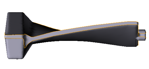
3.In the tab Geometry click Load from file and specify the path to the geometry file C:\QForm UK\12.0.1\geometry\blade\blade_op1.shl. The uploaded geometry will appear on screen. Click Forward

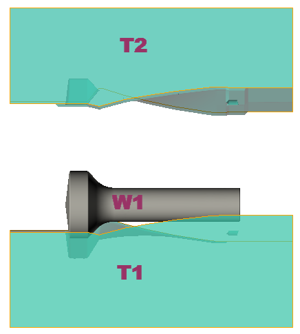
At the end operation the flash trimming has to be completed, so the clipping surface have to be specified. In the tab Geometry click Load from file and specify the path to the file C:\QForm UK\12.0.1\geometry\blade\blade_trim_surface.shl. The painted in the green color clipping surface will appear on the screen.

It is clear that it is necessary to carry out the preliminary positioning of the used clipping surface. Click ![]() Positioning in the drop-down list when you right-click on an object. In the positioning new window, rotate the workpiece around axis counterclockwise by 90° and move it along the axis Y by 73 mm and against the axis Z by 50 mm
Positioning in the drop-down list when you right-click on an object. In the positioning new window, rotate the workpiece around axis counterclockwise by 90° and move it along the axis Y by 73 mm and against the axis Z by 50 mm

Select Plain surface 1 in the list of objects and set Properties: Remove the material - Outside clipping surface, When to clip - After current operation

4.In the Workpiece parameters tab you need to set the material and workpiece temperature. Click next to Material[Select...]

In the new window that opens, double-click on the material Steels/Carbon steels/C45 (1-0503) cold+hot. After this, the selected material will appear in the tab Workpiece parameters

Set the workpiece temperature to 1200˚C. Click Forward
5.In the tab Tool parameters the drive type, temperature and lubricant must be select for each tool. To be noted that in this example Tool 1 - upper tool, and Tool 2 - bottom tool. Next to Drive-Tool 1 click [Select...], the equipment database window will open. Choose equipment Standard\Mechanical press\40MN and double click on it, after that the selected drive will appear in front of Drive-Tool 1

Tool 2 - fixed , and it isvalid in axes direction OZ. Next to Drive-Tool 2 click [Select...], in the equipment database window, select Fixed drives\+OZ and double click on it, the selected drive will appear in front of Drive-Tool 2

Next to Lubricant click [Select...] and double click to set the lubricant Hot forging/Steels/Graphite + Water(graphite-water). Lubricant will appear immediately for all tools.
Next to Material click [Select...] and double click to set the material L6HRC42. The Material will appear immediately for all tools.
Opposite Temperature set the temperature of the tools 150 °C.
In order to take into account the elastic deformation of the tools during the simulation, check the box in front of Coupled tools simulation. Click Forward

6.In the Stop conditions tab you should set final distance between the tools. Click Distance. After that, specify the value of the final distance (4 mm). Click Forward

7.In the Boundary conditions tab, it is necessary to assign the tools constraints. Choose a tool Tool 1, and a list of boundary conditions will appear below. Click Rigid fixing

Next, you need to select the domain shape. Click Surface

Holding down a key Shift, select the upper face with the left mouse button Tool 1. The selected face changes color. Click OK

The assigned boundary condition will be displayed on the object Tool 1

Similar actions must be completed again for the second tool. Select Tool 2, and a list of boundary conditions will appear below. Click Rigid fixing. Next you need to select the domain shape. Click Surface. Holding down a key Shift, select the bottom face with the left mouse button Tool 2. Click OK. The assigned boundary condition will be displayed on the object Tool 2. Click Forward
8.In the Blows tab set the cooling in air and in the tool. Click Forward

9.In the Simulation parameters tab all remains unchanged. Click OK.
Click the icon Save project on the tools panel, set the name and location for saving the project on your computer.
10.Click on the button Simulation![]() , and after that the simulation will start.
, and after that the simulation will start.
11.When the simulation of operation is compleated, open the tab Project and chose Operation 1 and click on the button Add operation to process chain

12.In the tab Process select Operation type - Cooling/Heating and activate Taking into account elastoplastic deformations, Problem type - 3D. Click Forward

13.In the tab Geometry you can see that only the workpiece is inherited from the previous operation

can be clicked Inherit from previous operation and see which objects are inherited

Close the inherited objects window, click Forward twice before going to the tab Stop conditions, because in the tab Workpiece parameters nothing additional needs to be specified.
14.In the tab Stop conditions it is necessary to set the time of the cooling process in air. Click Time. After that, specify the value of the cooling time (4000 s).

In the tab Boundary conditions all remains unchanged, so click Forward 2 times before going to the tab Process parameters.
15.Set value Maximum time step equal to 10 s to accelerate the simulation. This will also reduce the amount of simulation steps and, accordingly, the size of the results file on disk.

Click OK. Save the project and click on the button Simulation![]()