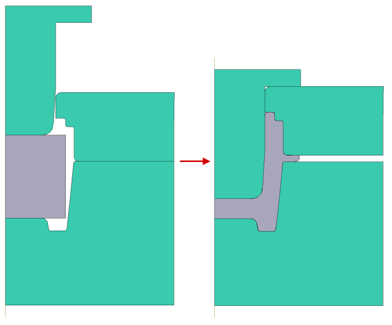
In forging processes exist technologies with a spring loaded tool. In the example below, considered the process of a bulk axisymmetric forging with a spring loaded tool, which is driven by interaction with the workpiece, and then moves from the driven tool 1.
Initial data
Operation |
Operation type |
General forming |
Additional parameters |
With thermal process |
|
Problem type |
2D axisymmetric |
|
Geometry |
Load from file |
spring_loaded.crs |
Workpiece parameters |
Material |
Steels\Carbon steels\C60 (1-0601) |
Temperature |
1100˚С |
|
Tool parameters |
Drive |
Tool 1 - Hydraulic press 50 MN Tool 2 - Fixed drive -OZ |
Lubricant |
Tool 1, 2, 3 - Graphite-water (Hot forging/Steels/Graphite + Water) |
|
Material |
Tool 1, 2, 3 - L6HRC42 |
|
Temperature |
Tool 1, 2, 3 - 200 ˚С |
|
Put in contact |
Tool 1, 3 - move backward first |
|
Coupled deformation |
Not |
|
Heat transfer to workpiece |
Simple |
|
Spring loaded tool |
Tool 2 |
|
Initial compression load |
0 MN |
|
Spring stiffness |
0 MN / MN/mm |
|
Movement of a tool by another connecting tool |
activated |
|
Stop conditions |
Distance |
11,5 mm from Tool 1 to Tool 3 |
Boundary conditions |
Environment |
Air 20˚C |
Blows |
Number of blows |
1 |
Cooling in air |
2 s |
|
Cooling on tool |
1 s |
|
Simulation parameters |
Integration method |
Implicit |
1.Click Create new process

2.In the tab Operation select Operation type - General forming, With thermal process andProblem type - 2D axisymmetric. Click Forward

3.In the tab Geometry click Load from file and specify the path to the geometry file C:\QForm UK\12.0.1\geometry\spring_loaded\spring_loaded.dxf. The uploaded geometry will appear on screen. ClickForward

4.In the tab Workpiece parameters you need to set the material and temperature of workpiece. Click opposite Material[Select...]

In the opened database window, select the material Steels\Carbon steels\C60 (1-0601) and double click on it, after that the material will appear in the tab Workpiece parameters

Set the workpiece temperature to 1100 ˚С. Click Forward

5.In the tab Tool parameters it is necessary to set the drive, temperature, lubricant, material for each tool, as well as set the spring loaded tool and its parameters. Opposite Drive- Tool 1 click [Select...], the equipment database window will open. Select equipment Standard\Hydraulic press\50MN and double click on it, after that the selected drive will appear opposite Drive- Tool 1

Tool 2 - is a spring loaded tool, and it moves from contact with the workpiece in the direction of the OZ axes , and then from contact with the drive Tool 1. Opposite Drive- Tool 2 click [Select...], in the equipment database window, select Fixed drives\-OZ and double-click on it, the selected drive will appear opposite Drive- Tool 2

Tool 3 - fixed, and it acts in the direction of the OZ axes . Opposite Drive- Tool 3 click [Select...], in the equipment database window, select Fixed drives\+OZ and double-click on it, the selected drive will appear opposite Drive- Tool 3

Opposite Lubricant click [Select...] and double click to set lubricant Hot forging/Steels/Graphite + Water (graphite-water). Lubricant will appear immediately for all tools.
Opposite Material click [Select...] and double click to set the material L6HRC42. The material will appear immediately for all tools. Opposite Temperature set tool temperature 200 °С.
For Tool 2 it is necessary to set put in contact condition - keep current position, otherwise Tool 2 will be in contact with Workpiece, which does not correspond to the technological process.

It's necessary to set Spring loaded tool for Tool 2 and activate movement of a tool by another connecting tool

Opposite Initial compression load and Spring stiffness set the value 0,1

Click Forward
6.In the Stop conditions tab you should set final distance between the tools. Click Distance. After that, specify the value of the final distance (11,5 mm) and select the tools between which it will be set: From tool - Tool 1, To tool - Tool 3. Click Forward

7.In the Boundary conditions tab all remains unchanged. Click Forward

8.In the tab Blows set the cooling in air (2 s) and on tool (1 s). Click Forward

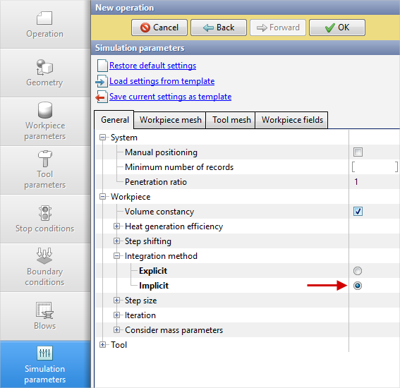
9.In the tab Simulation parameters must be select Integration method - Implicit,as it provides a more stable solution to problems with springs.
Click OK
10.Click on the button Simulation![]() , and the program will ask to save the project. Set the project name and click Save. The simulation will start after that.
, and the program will ask to save the project. Set the project name and click Save. The simulation will start after that.
