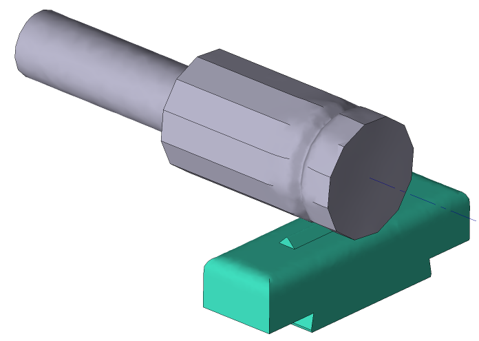
Cogging is one of the basic open die forging operation. Cogging is a multi-blow process in which the workpiece or part of it is lengthened by reducing the cross cut for further processing. Example of a multi-blow process of cogging a workpiece is below.
Operation 1 |
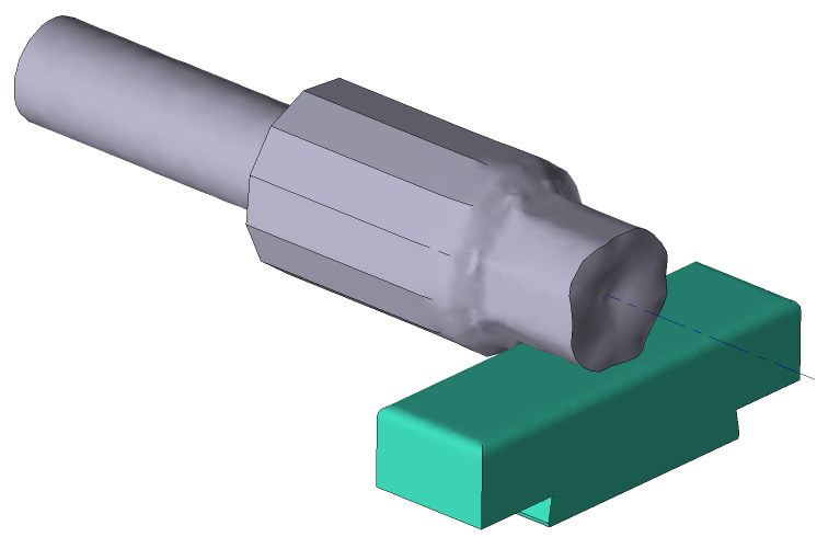
Operation 2 |
|
|
Initial data
Operation 1 |
||
|---|---|---|
Operation |
Operation type |
General forming |
Additional parameters |
With thermal process |
|
Problem type |
3D |
|
Geometry |
Load from file |
cogging_oper1.shl |
Workpiece parameters |
Material |
Steels\Ni - NiCr - NiCrMo\12Ni10 (1-5680) |
Temperature |
1150˚С |
|
Tool parameters |
Drive |
Tool 1 - Hydraulic press 50 MN Tool 2 - Fixed drive +OZ |
Lubricant |
Tool 1, 2 - Without lubricants (Hot forging/Steels/Unlubricated) |
|
Material |
Tool 1, 2 - 5140 HRC39 |
|
Temperature |
Tool 1, 2 - 200˚С |
|
Stop conditions |
Distance |
432 mm between Tool 1 and Tool 2, at point: X= 50 mm, Y= 50 mm |
Boundary conditions |
Environment |
Air 20˚C |
Workpiece |
Forging manipulator |
|
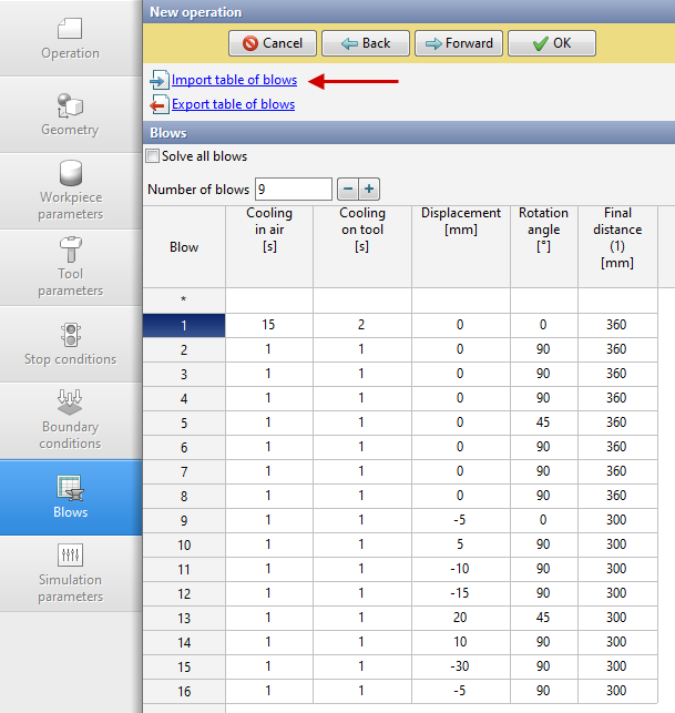
Blows |
Import blows table |
blows_table_1.xlsx |
Simulation parameters |
|
Default |
Operation 2 |
||
Operation |
Operation type |
General forming |
Additional parameters |
With thermal process |
|
Problem type |
3D |
|
Geometry |
Load from file |
cogging_oper2.shl |
Workpiece parameters |
Material |
Inherited from previous operation |
Temperature |
Inherited from previous operation |
|
Tool parameters |
Drive |
Tool 1 - Hydraulic press 50 MN Tool 2 - Fixed drive +OZ |
Lubricant |
Tool 1, 2 - Without lubricants (Hot forging/Steels/Unlubricated) |
|
Material |
Tool 1, 2 - 5140 HRC39 |
|
Temperature |
Tool 1, 2 - 200˚С |
|
Stop conditions |
Distance |
Individually for each blow between Tool 1 and Tool 2 |
Boundary conditions |
Environment |
Air 20˚C |
Workpiece |
Forging manipulator |
|
Blows |
Import blows table |
blows_table_2.xlsx |
Simulation parameters |
|
Default |
1.Click Create new process
2.In the tab Operation select Operation type - General forming, With thermal process and Problem type - 3D. Click Forward
3.In the tab Geometry click Load from file and specify the path to the geometry file C:\QForm UK\12.0.1\geometry\cogging\cogging_oper1.shl. The uploaded geometry will appear on screen. ClickForward

4.In the tab Workpiece parameters you need to set the material and temperature of workpiece. Click in front of Material[Select...]
In the database new window, select the material Steels\Ni - NiCr - NiCrMo\12Ni19 (1-5680) and click on it twice, after that the material will appear in the tab Workpiece parameters
Set the workpiece temperature to 1150˚C. Click Forward
5.In the tab Tool parameters it is necessary to select the drive type, temperature, lubricant, material for each tool. In front of Drive- Tool 1 click [Select...], the equipment database window will open. Choose equipment Standard\Hydraulic press\50MN and click on it twice, after that the selected drive will appear opposite Drive- Tool 1
Tool 2 - fixed, and it works in the direction of the OZ axes. In front of Drive- Tool 2 click [Select...], in the equipment database window, select Fixed drives\+OZ and double click on itthe selected drive will appear in front of Drive- Tool 2
Next to Lubricant click [Select...] and double click to set lubricant Hot forging/Steels/Unlubricated (without lubricant). Lubricant will appear immediately for all tools.
Next to Material click [Select...] and double click to set the material 5140HRC39. The Material will appear immediately for all tools. In front of Temperature set tool temperature 200°C.
Click Forward
6.In the Stop conditions tab you should set final distance between the tools. Click Distance. After that, specify the value of the final distance (432 mm) at point X= 50 mm, Y= 50 mm. Click Forward

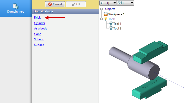
7.In the tab Boundary conditions need to create forgingForging manipulator. Highlight Workpiece, and a list of boundary conditions will appear below. Click Forgingmanipulator

In the tab Domain shape click Brick
In the tab Domain parameters set the domain size according to the picture below:
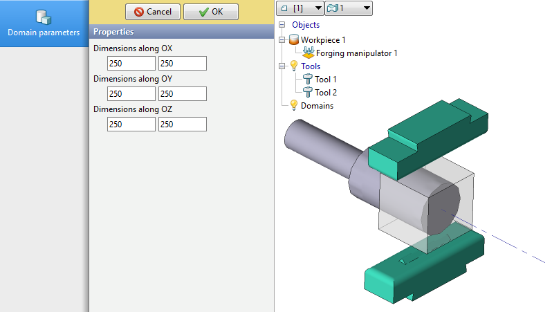
Click OK. Then position Forgingmanipulator. Switch to mode Positioning using the button on panel of the tools. You also need to enable Return at the end of the blow and ask Crosswise resistance factor equal to 1 in PropertiesForgingmanipulator.

8.In the tab Blows click Importtableof blows. SelectC:\QForm UK\12.0.1\geometry\cogging\blows_oper_1.xlsx. Click Forward

9.In the Simulation parameters tab all remains unchanged. Click OK
10.Click on the button Simulation![]() , and the program will ask to save the project. Set the project name and click Save. The simulation will start after that.
, and the program will ask to save the project. Set the project name and click Save. The simulation will start after that.

11.When the operation has been calculated, open the tab Project and press Add an operation to a chain

12.In the tab Operation select Operation type - General forming, With thermal process and Problem type - 3D.
To copy the forging manipulator from the first operation, click Copy data from previous operation. Leave only the item active Copy boundary conditions. Click Forward

13.In the tab Geometry click Load from file and specify the path to the geometry file C:\QForm UK\12.0.1\geometry\cogging\cogging_oper2.shl. The uploaded geometry will appear on screen. Click Forward

14.In the Workpiece parameters tab all remains unchanged: the workpiece and its temperature are inherited from the first operation. Click Forward
15.In the Tool parameters tab set all as for the first operation. Click Forward
16.In the Stop conditions tab you should set final distance between the tools. At the stop conditions Distance feature must be enabled Individually for each blow. Click Forward

17.In the Boundary conditions tab all remains unchanged. Onpress Forward
18.In the tab Blows click Importtableof blows. Select C:\QForm UK\12.0.1\geometry\cogging\blows_oper_2.xlsx. Click Forward
19.In the Simulation parameters tab all remains unchanged. Click OK
20.Save the project and click on the button Simulation![]()