Cross wedge rolling (CWR) is the process of deforming metal with wedge tools. The tool can be flat or made in the form of rolls, depending on the type of CWR equipment.
|
Examples of processes: 1 - CWR with flat wedges; 2 - CWR with rolls (roll-wedge cross rolling). |

CWR processes that can be simulated in the general forming module include other similar processes in which the rotation of the workpiece occurs due to contact with wedges. The rotation is strictly perpendicular to the axis of the workpiece, which distinguishes this process from helical rolling.
Let's consider the work in the general forming module on the example of project assembly flat cross wedge rolling. The parameters of cross wedge rolling are shown in the figure: D = 26 mm - diameter of the billet, d = 20 mm - diameter of the resulting shaft section, s = 10 mm - width of the resulting shaft section, α = 40˚ , β = 2˚ - angles of the wedge.
Operation 1 |
|

Initial data
Operation 1 |
||
Operation |
Operation type |
General forming |
Additional parameters |
With thermal process |
|
Operation type |
3D |
|
Geometry |
Load from file |
CWR.stp. |
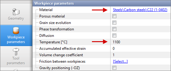
Workpiece parameters |
Material |
Steels/Carbon steels/C45 (1-0503) |
Temperature |
1150 ˚С |
|
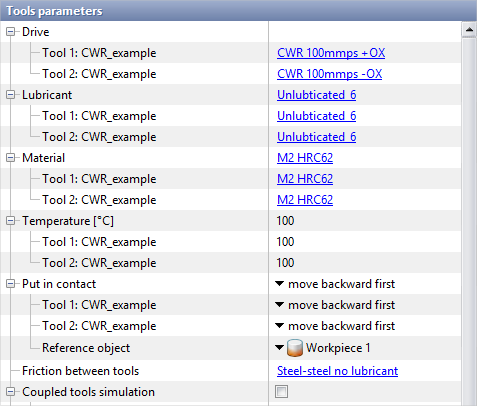
Tool parameters |
Lubricant |
Friction Law - Levanov |
Friction factor - 0.9 and 6 |
||
Heat transfer coefficient - 50000 W/(m2-K) |
||
Material |
M2 (AISI) |
|
Temperature |
100 ˚С |
|
Heat transfer to workpiece |
Simple |
|
Mill parameters for CWR |
Maximum load [MN] |
1 |
Tool velocity [mm/sec] |
100 |
|
Stop conditions |
Tool stroke [mm] |
490 |
Boundary conditions |
Environment |
Air 20 ˚C |
Simulation parameters (General) |
Rotation (Step shifting) |
Activated |
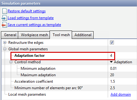
Simulation parameters (Tool mesh) |
Adaptation factor |
4 |
1.Click Create new process

2.In the Operation tab, select Operation Type - Deformation, With thermal process, Problem Type - 3D. Click Forward.

3.In the Geometry tab, click Load from file and specify the path to the geometry file C:\QForm UK\12.0.1\geometry\cross_wedge_rolling\cross_wedge_rolling.stp. The loaded geometry for Tool 1 will appear on the screen. Convert it to Tool 1. Since the top and bottom tools are the same, copy this geometry, name it Tool 2 and rotate it 180 degrees about the OZ axis. This should result in 2 tools: Tool 1(will move along the -OX axis) and Tool 2 (will move along the +OX axis) .

To do this, change the position of the grip Tool 2 by specifying the coordinates 0,15,0 as shown:

Rotate Tool 2 by 180˚. Tool 1and Tool 2 - in contact with each other. Now you can shift the tool by a distance equal to the diameter d = 20 mm:

4.The workpiece is created parametrically. To do this, click Parametric geometry and create a cylinder as shown in the figure.

In this case, convert the created cylinder to Workpiece 1 and add a symmetry plane.

5.In the Workpiece parameters tab, assign material and temperature and click Forward.
6.In the Tool parameters tab, set the tool to be imported beforehand. To do this, in the Equipment Database, click import (1) and select the files CWR 100mmps +OX.qdat-bin and CWR 100mmps -OX.qdat-bin (from the same folder <%DEFAULTDIR%>geometry\cross_wedge_rolling ). Save the imported tools to the project file (2) and assign to Tool 1 - CWR 100mmps +OX and for Tool 2 - CWR 100mmps -OX (3).

7.In the Tool parameters tab, we also set the lubricant, which must be created beforehand. In this example, there are no additional guides to rotate the forging, so rotation will be set by the entire tool surface. For this purpose, we create (1) a lubricant type Unlubticated_6 with a friction factor of 6 (2) set for the whole tool (3). If there are guideways and lateral grooved or toothed surfaces - lubrication Unlubticated_6 is only specified on them. On other surfaces, you can set the standard lubrication type Unlubricated (default friction factor 0.9), or set Unlubticated_6 everywhere .
Enter the parameters according to the initial data (2), click Save and then Assign.

Set the remaining parameters for the tools according to the original data and click Forward.
8.In the Stop conditions tab, assign a time stop to the process and click Forward. The Boundary conditions and Blows tabs remain unchanged.

9.In the Simulation parameters tab, under General activate the option Rotation (Step shifting).

10. In the Simulation parameter tab, under Tool mesh change Adaptation factorto 4. This is necessary to more accurately determine contact with the tool.
|
Information |
In this simple task Adaptation factorincreased to improve the tool mesh and better define the contact area. Note that for more complex wedge geometry, such a strong increase in the adaptation factor can significantly increase the simulation time. |
|
11.Click Ok and run the simulation.
![]()