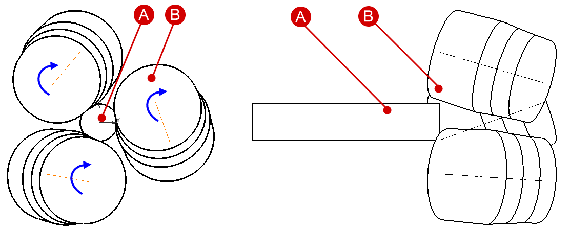
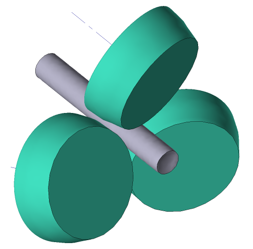
Cross rolling is a process of metal forming by obliquely positioned rolls, where the axes of the rolls form skew lines with the axis of the workpiece. The diagram of cross rolling in a three-high mill is shown in the figure below.
|
A - workpiece; B - rolls. |
Cross rolling processes that can be simulated in the cross rolling module also include piercing processes - processes of obtaining hollow tubes from solid cylindrical blanks.
Let's consider the work in the module on the example of cross rolling.
Operation 1 |
|
Initial data
Operation 1 |
||
Operation |
Operation type |
Cross rolling |
Additional parameters |
With thermal process |
|
Problem type |
3D |
|
Geometry |
Load from file |
cross_rolling.shl |
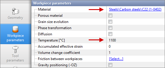
Workpiece parameters |
Material |
Steels\Carbon steels\C22 (1-0402) |
Temperature |
1100˚С |
|
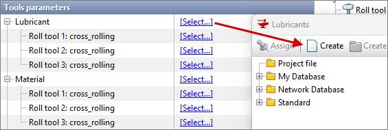
Tool parameters |
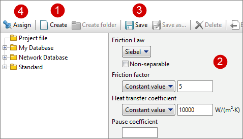
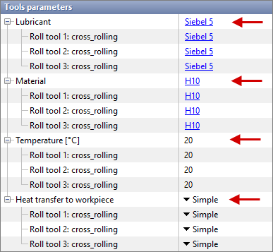
Lubricant |
Friction law - Siebel |
Friction factor - 5 |
||
Heat transfer coefficient - 10000 W/(m2 •K) |
||
Material |
H10 (AISI) |
|
Temperature |
20˚С |
|
Heat transfer to workpiece |
Simple |
|
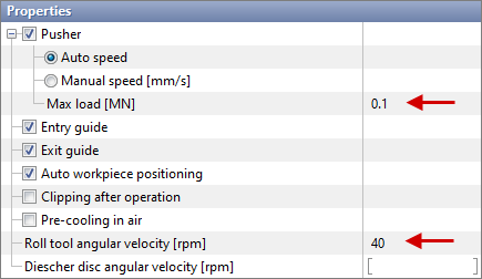
Rolling parameters |
Max load [MN] |
0.1 |
Roll tool angular velocity [rpm] |
40 |
|
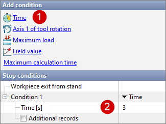
Stop conditions |
Time [s] |
3 |
Boundary conditions |
Environment |
Air 20˚С |
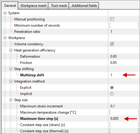
Simulation parameters (General) |
Multistep shift |
1 |
Maximum time step [s] |
0.005 |
|
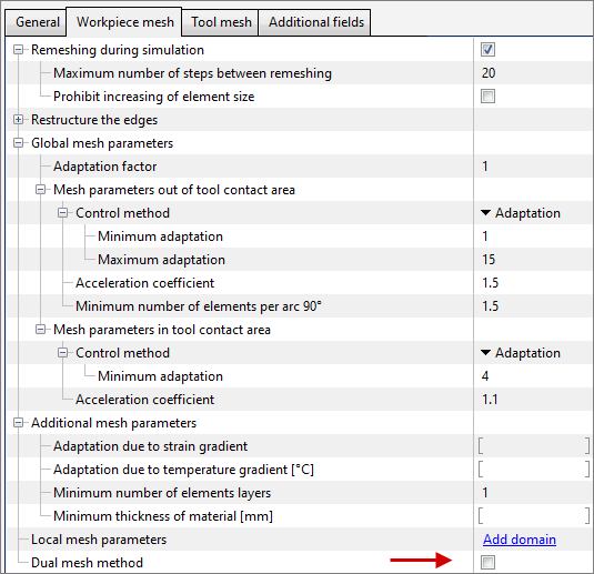
Simulation parameters (Workpiece mesh) |
Dual mesh method |
Disable |
1.Click Create new process

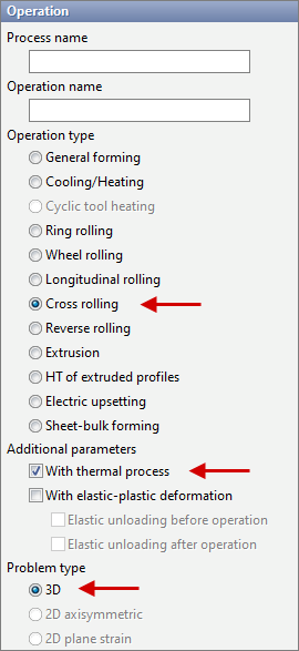
2.In the Operation tab select Operation type - Cross rolling, With thermal process, Problem type - 3D. Click Forward.
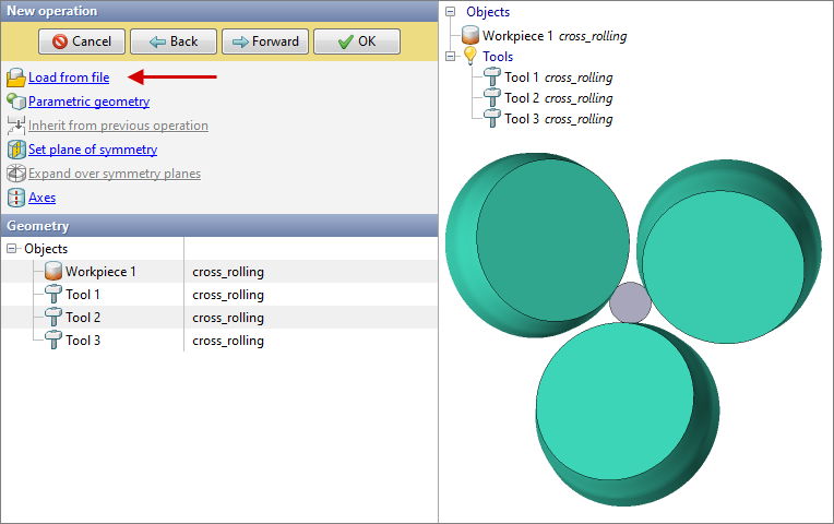
3.In the Geometry tab click Load from file and specify the path to the geometry file C:\QForm UK\12.0.1\geometry\cross_rolling\cross_rolling.shl. The loaded geometry will appear on the screen. Click Forward.
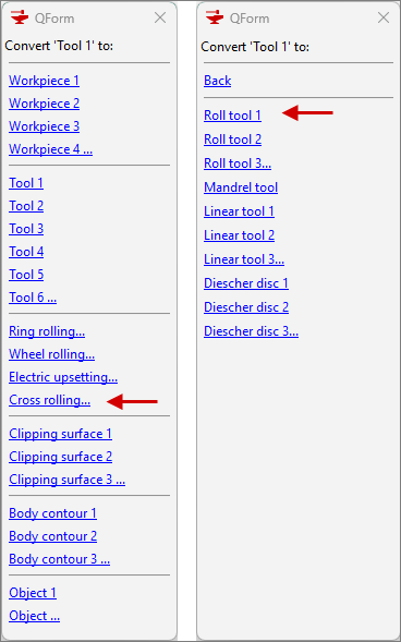
4.Then convert the tools into special object types for this module. To do this, select the tool and find the Convert command in the properties below.
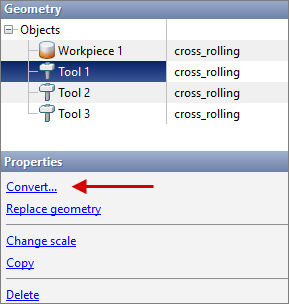
In this case, we convert the tools into roll tools.
Repeat the steps for all tools.
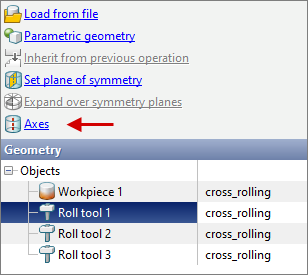
5.Next, set the axes for the rolls. To do this, click on Axes:
In the opened window select the required tool and click Compute:
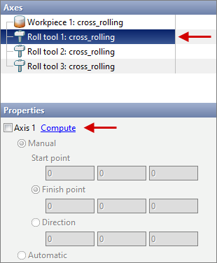
Repeat the steps for all the rolls and click Forward.
6.Set the material and temperature in the Workpiece parameters tab and click Forward.
7.In the Tool parameters tab set the lubricant, which must first be created.
Enter the parameters in accordance with the initial data, click Save and then Assign.
Set the remaining tool parameters according to the initial data and click Forward.
8.In the Rolling parameters tab set the equipment kinematics according to the initial data. Parameters that are not specified in the initial data remain as defaults.
Click Forward.
9.In the Stop conditions tab assign a time to stop the process and click Forward.
10.In the Simulation parameters tab in the General section change the values of the Multistep shift and Maximum time step [s] parameters to the values specified in the initial data.
11. In the Simulation parameters tab in the Workpiece mesh section disable the Dual mesh method.
12.Click OK and start the simulation.
![]()