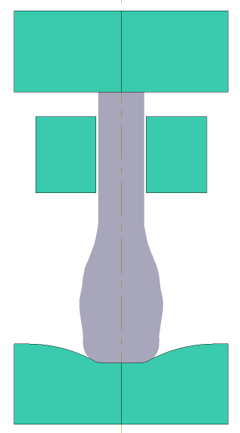
Electric upsetting is a progressive metal forming process used to accumulate a significant amount of material at the ends or in the middle of a workpieces with an extended axis. Due to the local heating in this process, it is possible to get a large strain for one step. Below is an example of electric upsetting followed by forging:
Operation 1 |
Operation 2 |
|
|
Initial data
Operation 1 |
||
|---|---|---|
Operation |
Operation type |
Electric upsetting |
Additional parameters |
With thermal process |
|
Problem type |
2D axisymmetric |
|
Geometry |
Load from file |
electricalal_upsetting_op1.dxf |
Workpiece parameters |
Material |
Mo - CrMo\34CrMo4 (1-7220) cold+hot |
Temperature |
20˚С |
|
Tool parameters |
Drive |
Pusher - Universal drive Anvil - Universal drive Current clamp - Fixed drive |
Lubricant |
Pusher - Without lubricants (Hot forging/Steels/Unlubricated) Anvil - Without lubricants (Hot forging/Steels/Unlubricated) Current clamp - Without lubricants (Hot forging/Steels/Unlubricated) |
|
Material |
Pusher - H13 HRC50 Anvil - H13 HRC50 Current clamp - H13HRC50 |
|
Temperature |
Pusher - 20˚С Anvil - 150˚С Current clamp - 20˚С |
|
Electric upsetting |
Current type |
Alternating current, Frequency - 50 Hz |
Current characteristic |
Current: Current.xlsx |
|
Stop conditions |
Distance |
32 mm between Pusher and Current clamp |
Boundary conditions |
Environment |
Air 20˚C |
Blows |
Number of blows |
1 |
Cooling in air |
0 s |
|
Cooling on tool |
0 s |
|
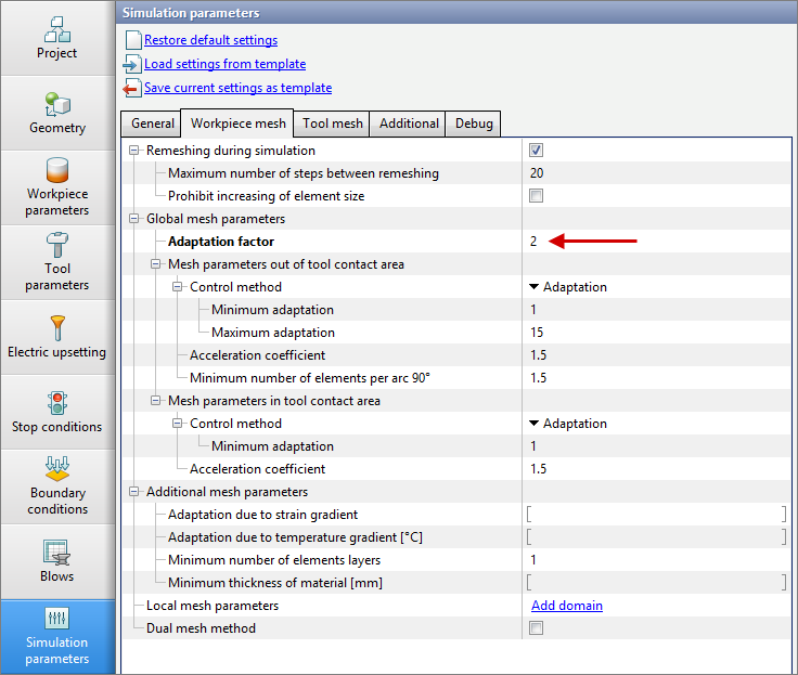
Simulation parameters |
Mesh in the workpiece |
Adaptation factor: 2 |
Operation 2 |
||
Operation |
Operation type |
General forming |
Additional parameters |
With thermal process |
|
Problem type |
2D axisymmetric |
|
Geometry |
Load from file |
electrical_upsetting_op2.dxf |
Workpiece parameters |
Material |
Inherited from previous operation |
Temperature |
Inherited from previous operation |
|
Place upside down before operation |
Activate |
|
Tool parameters |
Drive |
Tool 1 - Screw drive 1600 t Tool 2 - Fixed drive +OZ |
Lubricant |
Tool 1, 2 - Graphite-water (Hot forging/Steels/Graphite + Water) |
|
Material |
Tool 1, 2 - H13HRC50 |
|
Temperature |
Tool 1, 2 - 200˚С |
|
Stop conditions |
Distance |
0 mm between Tool 1 and Tool 2 |
Boundary conditions |
Environment |
Air 20˚C |
Blows |
Number of blows |
1 |
Cooling in air |
5 s |
|
Cooling on tool |
2 s |
|
Simulation parameters |
Mesh in the workpiece |
Adaptation factor: 3 |
Mesh in tool |
Adaptation factor: 3 |
|
1.Click Create new process
2.In the tab Operation select Operation type - Electric upsetting, Problem type - 2D axisymmetric, With thermal process. Click Forward

3.In the tab Geometry click Load from file and specify the path to the geometry file C:\QForm UK\12.0.1\geometry\electrical_upsetting\electrical_upsetting_op1.dxf. The uploaded geometry will appear on screen. Click Forward

Next you need to select Tool 1 , then click on Convert... , and in the opened window, select Electric upsetting...

Next click Pusher

Next you need to select Tool 2 , then click on Convert... , and in the window that opens, select Electric upsetting.. . Next click Current clamp
Next, you need to select Tool 3, then click on Convert..., and in the window that opens, select Electric upsetting. Next click Anvil
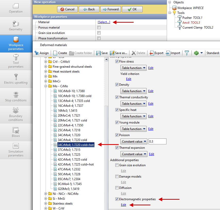
4.In the tab Workpiece parameters you need to set the material and temperature of workpiece. Click next to Material [Select...]
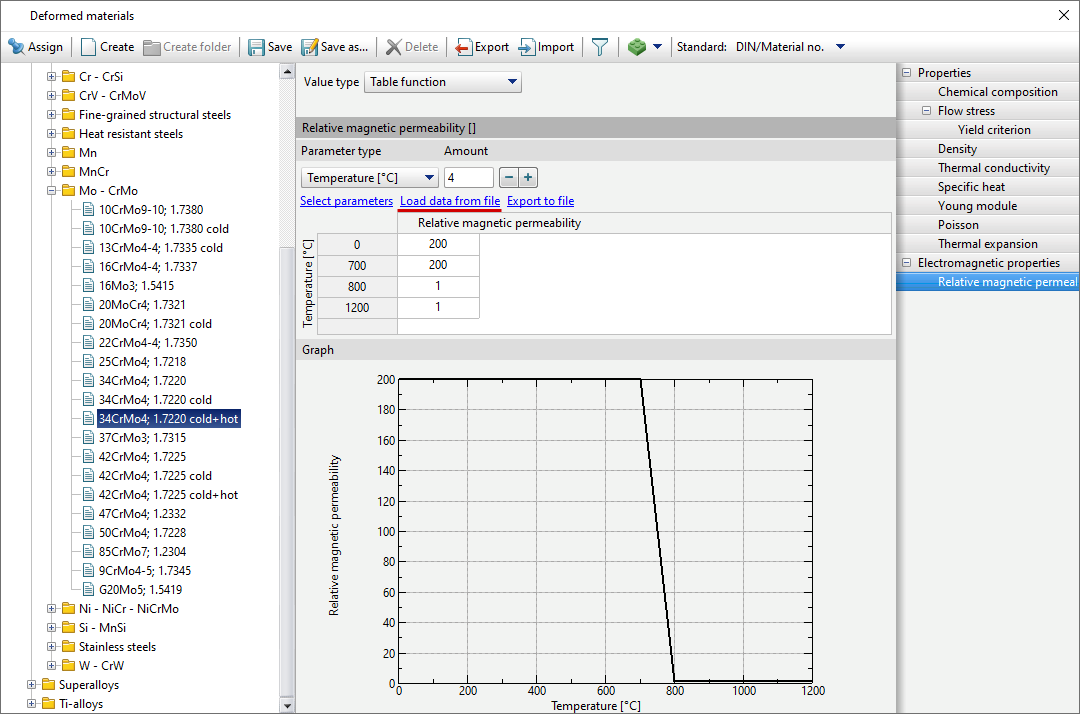
In the opened database window, select the material Steels \ Mo - CrMo \34CrMo4 (1-7220) cold+hot. In the material properties, activate Electromagnetic properties. Next, click on Edit.
In the window that appears, activate Relative magnetic permeability. Next, by selecting Table function, click on Edit.
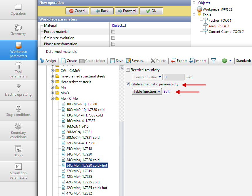
In the menu that appears, click Download data from file and select C:\QForm UK\12.0.1\ geometry\electrical_upsetting\Relative_magnetic_permeability .xlsx , after which a table of the dependence of relative magnetic permeability on temperature will appear.
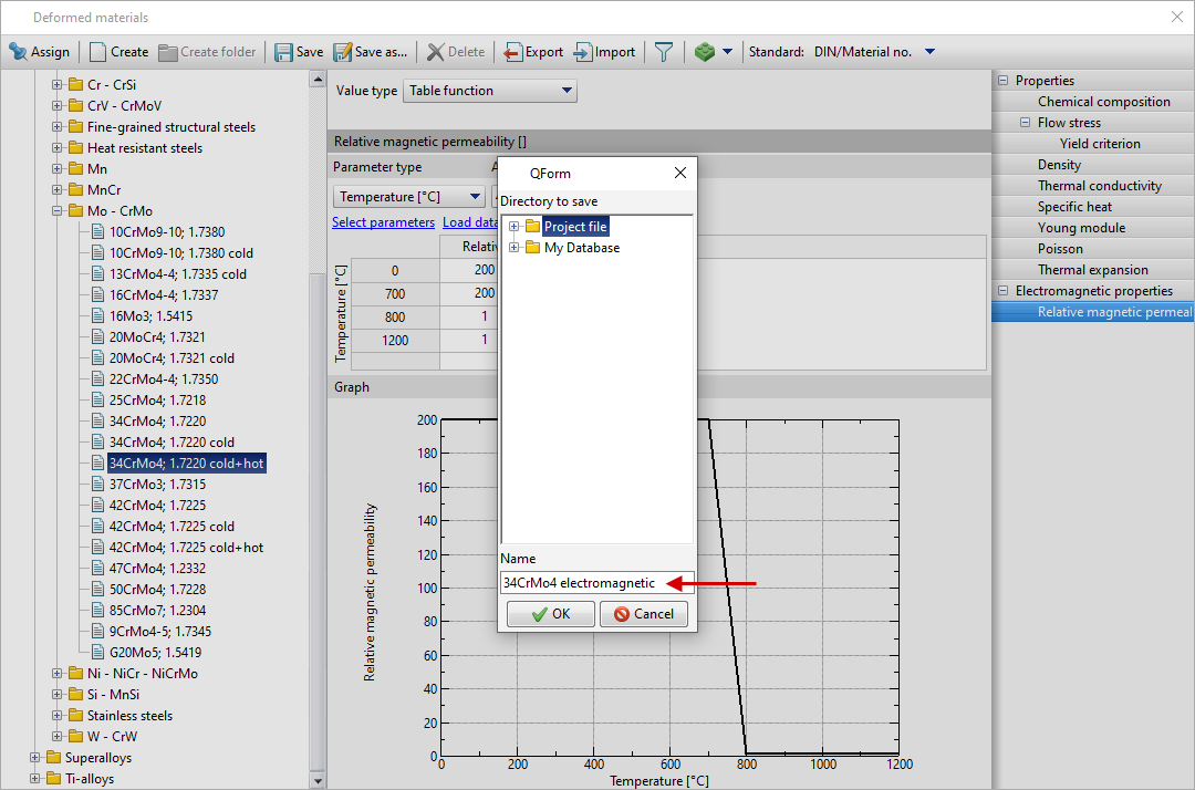
Next click Save as... and set the name 34CrMo4 electromagnetic , click OK . The created material will appear in the folder Project file , which must be assigned to Workpiece material .
Set the workpiece temperature 20˚С . Click Forward
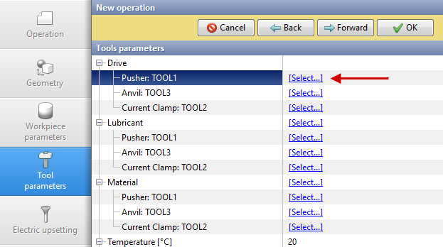
5.In the tab Tool parameters it is necessary to select the drive type, temperature, lubricant, material for each tool. Next to Drive - Pusher click [Select...] , the equipment database window will open.
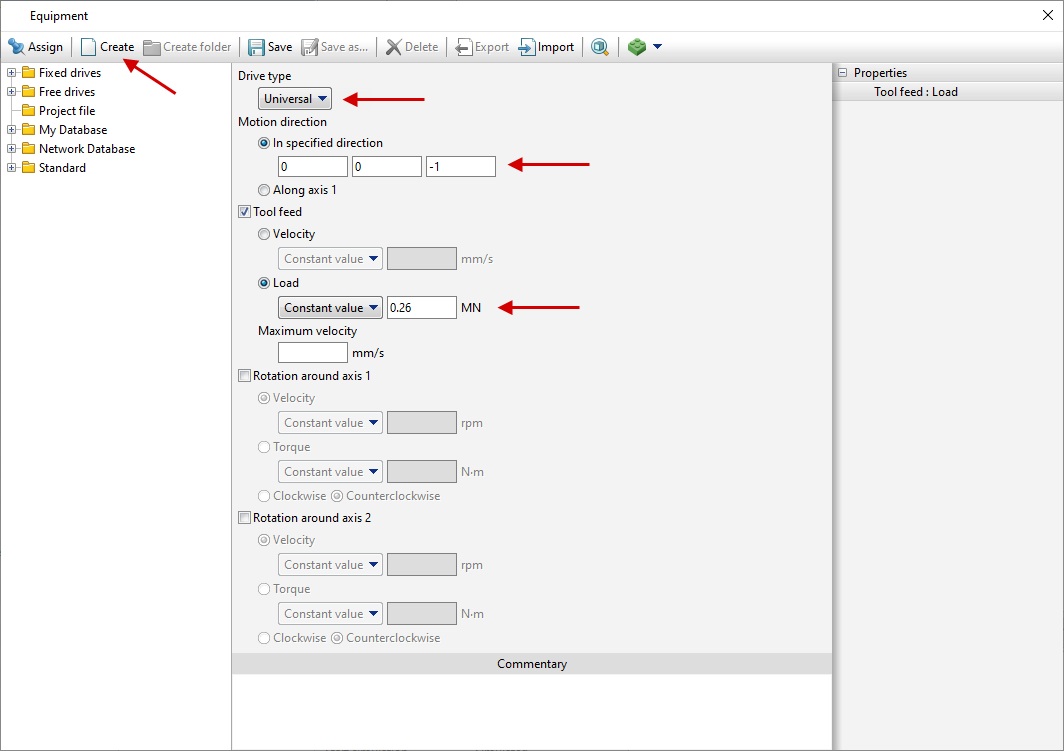
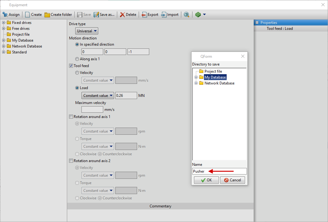
Click Create select Universal in Drive type . Next, set the motion direction: (0, 0, - 1), as Pusher moving in the direction -OZ. Also set Load 0.26 MN , having activated Tool feed .
Next click Save and set the name Pusher , click OK . The created drive will appear in the folder Project file, and it should be assigned to Pusher.
Anvil - also moves in the direction -OZ. Next to Drive-Anvil click [Select...], in the equipment database window, click Create select Universal in Drive type. Next, set the motion direction: (0, 0, - 1), activate Tool feed and select Velocity. Next, choosing Table function click on Edit.

In the menu that appears, click Download data from file and chooseC:\QForm UK\12.0.1\geometry\electrical_upsetting\anvil.xlsx, then a table of velocity versus time will appear.

Next click Save and give a name Anvil, click OK. The created drive will appear in the folder Project file and it should be assigned to Anvil.

Current clamp - fixed. Next to Drive - Current Clamp click [Select...] , in the equipment database window, click Create select Universal , set the motion direction: (0, 0, 1)

Next click Save and give a name fixed, click Ok. The created drive will appear in the folder Project file, it should be assigned to Current clamp.
Next to Lubricant click [Select...] and double click to set lubricant Hot forging/Steels/Unlubricated (without lubricants). Lubricant will appear immediately for all tools.
Next to Material click [Select...] and double click to set the material H13 HRC50. The Material will appear immediately for all tools.
Next to Temperature set tool temperature 150°C for Plate, for others 20°C.
Next to Put in contact indicate do not put in contact for all objects.

Click Forward
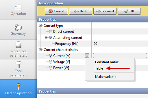
6.In the tab Electric upsetting the default value of the frequency is set 50 Hz for Alternating current. You have to specify Table next to Current for Current characteristics.
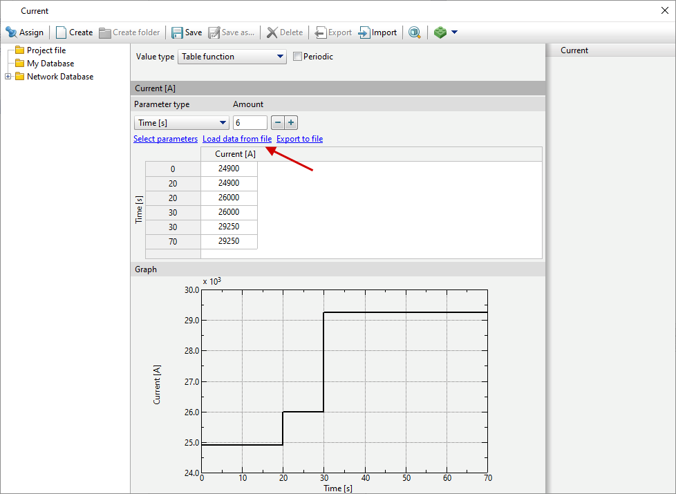
In the window that opens, click Download data from file and choose C:\QForm UK\12.0.1\geometry\electrical_upsetting\current.xlsx, then a table of current versus time will appear.
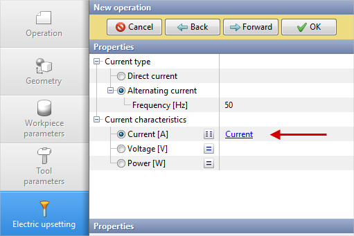
Next click Save and give a name Current, click OK. Assign the created characteristics to Current.
7.In the tab Stop conditions it is necessary to set the final distance between Pusher and Current clamp. Click Distance. After that, specify the value of the final distance 32 mm. Click Forward

8.In the Boundary conditions tab all remains unchanged. Click Forward.
9.In the tab Blows all remains unchanged. Click Forward
10.In the tab Simulation parameters you need to set 2 next toAdaptation factor for Workpiece mesh. Click OK
11.Click on the button Simulation![]() . Since the specific electrical resistance was not specified in the material properties , the software will issue a corresponding warning and the calculation of this property will be performed automatically according to the Wiedemann-Franz law. Click on Ignore and start simulation, The software will offer to save the project. Set the project name and click Save. The simulation will start after that.
. Since the specific electrical resistance was not specified in the material properties , the software will issue a corresponding warning and the calculation of this property will be performed automatically according to the Wiedemann-Franz law. Click on Ignore and start simulation, The software will offer to save the project. Set the project name and click Save. The simulation will start after that.

12.After the operation has been calculated, open the tab Project and highlight Process 1. click below Add operation to chain.
13.In the tab Process select Operation type - General forming , Problem type - 2D axisymmetric, with thermal process . Click Forward
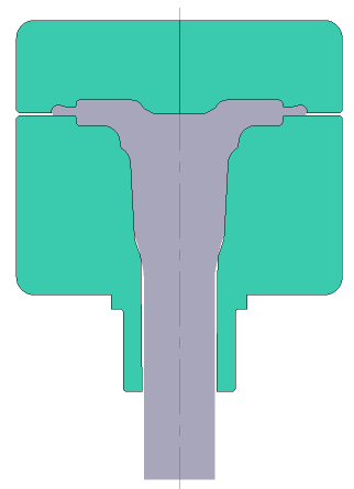
14.In the tab Geometry click Load from file and specify the path to the geometry file C:\QForm UK\12.0.1\geometry\electrical_upsetting\elecrtical_upsetting_op2.dxf. The uploaded geometry will appear on screen. Click Forward

15.In the tab Workpiece parameters all properties remain unchanged: the workpiece and its temperature are inherited from the first operation. In this case, you need to activate Place upside down before operation. Click Forward
16.In the tab Tool parameters it is necessary to select the drive type, temperature, lubricant, material for each tool. Next to Drive- Tool 1 click [Select...], the equipment database window will open. Choose equipment Standard\Screw press\1600t and double click on it, after that the selected drive will appear next to Drive- Tool 1. Tool 2 - fixed, and it works in the direction of the OZ axes . Next to Drive- Tool 2 click [Select...] , in the equipment database window , select Fixed drives\+OZ and double click on it, the selected drive will appear next to Drive- Tool 2.
Next to Lubricant click [Select...] and double click to set lubricant Hot forging/Steels/Graphite + Water (graphite-water ). Lubricant will appear immediately for all tools.
Next to Material click [Select...] and double click to set the material H13 HRC50. The Material will appear immediately for all tools. Next to Temperature set the tool temperature 200°С.

Click Forward
17.In the tab Stop conditions it is necessary to set the final distance between the tools - 0mm. Click Forward
18.In the Boundary conditions tab all remains unchanged. Click Forward
19.In the tab Blows select cooling time in air (5 s) and in the tool (2 s). Click Forward
20.In the tab Process parameters next to Adaptation factor for workpieces and tool, specify 3.
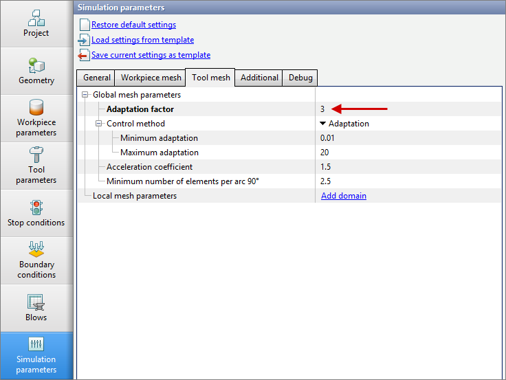
Click OK
21.Save the project and click on the button Simulation![]()