Rolling is one of the basic methods of metal forming. During the rolling process, the workpiece is deformed between two or more rotating rolls. In the programm QForm UK There are three module modules for rolling simulation: Longitudinal rolling, Reverse rolling and Cross rolling. Below is an example of longitudinal rolling in a module General forming.
Operation 1 |
Operation 2 |
|
|
Initial data
Operation 1 |
||
|---|---|---|
Operation |
Operation type |
General forming |
Problem type |
3D |
|
Geometry |
Load from file |
rolling.shl |
Workpiece parameters |
Material |
Steels\Carbon steels\C75 (1-0605) |
Temperature |
1200˚С |
|
Tool parameters |
Drive |
Tool1, 2 - Universal drive |
Lubricant |
Tool1, 2 - Hot rolling/Siebel m=0.8 |
|
Material |
Tool1, 2 - H13 HRC50 |
|
Temperature |
Tool 1, 2 - 70˚С |
|
Stop conditions |
Axis 1 of tool rotation |
190˚ for Tool 1 |
Boundary conditions |
Workpiece |
Pusher |
Blows |
Number of blows |
1 |
Pre-cooling in air |
5 s |
|
Pre-cooling on tool |
1 s |
|
Simulation parameters |
General |
Weight: disable |
Operation 2 |
||
Operation |
Operation type |
General forming |
Problem type |
3D |
|
Geometry |
Load from file |
Inherited from previous operation |
Workpiece parameters |
Material |
Inherited from previous operation |
Temperature |
Inherited from previous operation |
|
Tool parameters |
Drive |
Inherited from previous operation |
Lubricant |
Inherited from previous operation |
|
Material |
Inherited from previous operation |
|
Temperature |
Inherited from previous operation |
|
Stop conditions |
Axis 1 of tool rotation |
180˚ for Tool 1 |
Boundary conditions |
Workpiece |
Pusher |
Blows |
Number of blows |
1 |
Pre-cooling in air |
5 s |
|
Pre-cooling on tool |
0 s |
|
Simulation parameters |
General |
Weight: disable |
1.Click Create new process
2.In the tab Operation select Operation type - General forming, Problem type - 3D. Click Forward

3.In the tab Geometry click Load from file and specify the path to the geometry file C:\QForm UK\12.0.1\geometry\rolling\rolling.shl. The loaded geometry will appear on screen. Click Forward
4.In the tab Workpiece parameters the material and workpiece temperature should be set. Click next to Material [Select...]
In the database window, navigate to Steels\Carbon steels\C75 (1-0605) and double-click the grade, after which the selected material will be listed on the Workpiece parameters tab.
Set workpiece temperature 1200˚С. Click Forward.
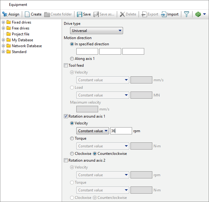
5.In the tab Tool parameters it is necessary to select the drive type, temperature, lubricant, material, heat transfer to workpiece for each tool. Next to Drive - Tool 1 click [Select...], the equipment database window will open.

Click Create select Universal in Drive type. Next, set Rotation around axis 1 - 36 rpm, Counterclockwise.
Next click Save and set a name roll1, click OK. The created drive will appear in the folder Project file, it must be assigned to Tool 1.
For Tool 2 - you need to create a drive in the same way as for Tool 1, just set Rotation around axis 1 clockwise. Next click Save and set a name roll2, click OK. The created drive will appear in the folder Project file, it must be assigned to Tool 2.
Next to Lubricant click [Select...] and double click to set lubricant Hot rolling/Siebel m=0.8. The lubricant will be automatically assigned to every tool in the list.
Next to Material click [Select...] and double click to set the material H13 HRC50. The material will be automatically assigned to every tool in the list.
Next to Temperature [C°] set temperature 70°C.
Next to Heat transfer to workpiece, set Constant temperature.
Click Forward.
6.In the tab Stop conditions click Axis 1 of tool rotation. After that enter the value 190°and select Tool 1. Click Forward

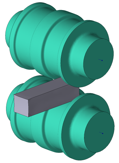
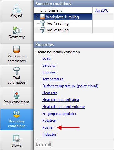
7.On the Boundary conditions tab, create a Pusher. To do this, select Workpiece and a list of boundary conditions will appear below. Click Pusher.
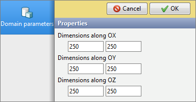
In the tab Domain shape click Brick and set the domain size as in the picture below:
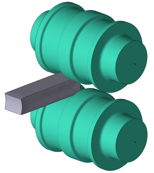
Click OK. Then position the Pusher using the Positioning mode as shown in the picture below:

8.In the properties of the boundary condition Pusher, it is necessary to set the Turn-off time equal to (3 s), specify the Pusher axis direction X (-1), and set the Pusher Velocity (500 mm/s). Click Forward

9.In the tab Blows set Pre-cooling in air time (5s) and Pre-cooling on the tool (1s). Click Forward
10.In the tab Simulation parametersWeight must be disabled. To do this, go to the section General and uncheck the box next to Weight. Click OK
11.Click on the button Start simulation![]() , and the programm will ask to save the project. Set the project name and click Save. The simulation will start.
, and the programm will ask to save the project. Set the project name and click Save. The simulation will start.
12.After the operation is simulated, open the tab Project and select Process 1. Below click Add operation to process chain
13.In the tap Operation select Operation type - General forming, Problem type - 3D. Next, click Copy data from previous operation and select Copy boundary conditions and Copy tools. Click Forward

14.In the tab Geometryclick Positioning mode Move the workpiece 620 mm along the +OY axis and 1400 mm along the –OX axis. Next, put the workpiece in contact with the top roll along the -OX axis. Click Forward
|
|
|
The workpiece moved 620 mm along the +OY axis and 1400 mm along the -OX axis |
|
Put the workpiece into contact with the upper roll |


15.In the tab Workpiece parameters all remains unchanged: the workpiece and its temperature are inherited from the first operation. Click Forward
16.In the tab Tool parameters all remains unchanged: the tool parameters are copied from the previous operation. Click Forward
17.In the tab Stop conditions click Axis 1 of tool rotation. After that enter the value 180 and select Tool 1. Click Forward
18.In the tap Boundary conditions, position the Pusher similarly to the first operation. Click Forward
19.In the tab Blows set Pre-cooling in air time (5s) and Pre-cooling on tool (0s). Click Forward
20.In the tab Simulation parameters all remains unchanged. Click OK
21.Save the project and click on the button Start simulation![]()