Reducer rolling is used to prepare the workpiece for subsequent deformation, and also as a final operation. In the first case, reducer rolling serves as a preliminary operation that redistributes the metal along the workpiece length for subsequent forging on other equipment. This technological operation is used instead of cogging and preforging.
The use of preliminary profiling of workpieces on forging rolls is advisable in the manufacture of elongated forgings. The use of rolled workpieces for subsequent forging saves metal, increases labor productivity, and reduces the cost of forgings. In the process of reducer rolling, the cross sections of the original workpieces are reduced while it is simultaneously elongated due to the workpieces being compressed by a rotating tool - rolls. Calibers are used for reducer rolling of workpieces with constant cross cut section.
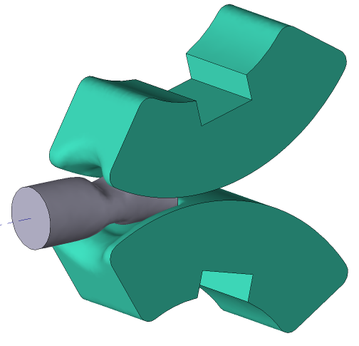
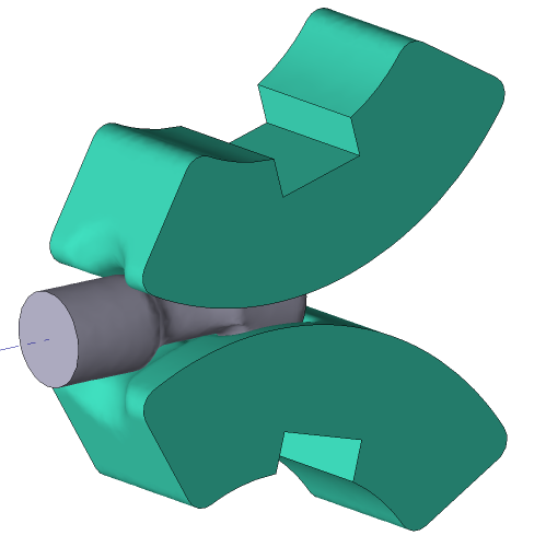
The following is an example of reducer rollingsimulation.
Operation 1 |
Operation 2 |
|
|
Initial data
Operation 1 |
||
Operation |
Operation type |
General forming |
Additional parameters |
With thermal process |
|
Problem type |
3D |
|
Geometry |
Load from file |
reduce_rolling_op1.shl |
Workpiece parameters |
Material |
Steels\Carbon steels\C22 (1) |
Temperature |
1000 ˚С |
|
Tool parameters |
Drive |
Tool 1 - Rotating equipment 65 rpm Tool 2 - Rotating equipment 65 rpm |
Lubricant |
Tools 1, 2 - Graphite+water (Hot forging/Steels/Graphite + Water) |
|
Material |
Tools 1, 2 - D2HRC59 |
|
Temperature |
Tools 1, 2 - 200 ˚С |
|
Coupled deformation |
Not |
|
Heat transfer to workpiece |
Simple |
|
Stop conditions |
Tool rotation |
Rotation Tool 1 at 45˚ |
Boundary conditions |
Environment |
Air 20 ˚С |
Workpiece |
Forging manipulator |
|
Blows |
Number of blows |
1 |
Cooling in air |
0 s |
|
Cooling on tool |
0 s |
|
Simulation parameters |
|
Default |
Operation 2 |
||
Operation |
Operation type |
General forming |
Additional parameters |
With thermal process |
|
Problem type |
3D |
|
Geometry |
Load from file |
reduce_rolling_op2.shl |
Workpiece parameters |
Material |
Inherited |
Temperature |
Inherited |
|
Tool parameters |
Drive |
Tool 1 - Rotating equipment 65 rpm Tool 2 - Rotating equipment 65 rpm |
Lubricant |
Tools 1, 2 - Graphite+water (Hot forging/Steels/Graphite + Water) |
|
Material |
Tools 1, 2 - D2HRC59 |
|
Temperature |
Tools 1, 2 - 200 ˚С |
|
Coupled deformation |
Not |
|
Heat transfer to workpiece |
Simple |
|
Stop conditions |
Tool rotation |
Rotation Tool 1 at 45˚ |
Boundary conditions |
Environment |
Air 20 ˚С |
Workpiece |
Forging manipulator |
|
Blows |
Number of blows |
1 |
Cooling in air |
0 s |
|
Cooling on tool |
0 s |
|
Rotate through angle |
90˚ |
|
Simulation parameters |
|
Default |
1.Click Create new process
2.In the Operation tab select Operation type - General forming, With thermal process, Problem type - 3D. Click Forward.
3.In the Geometry tab click Load from file and specify the path to the geometry file reduce_rolling_op1.shl (default:C:\QForm UK\12.0.1\geometry\reduce_rolling\reduce_rolling_op1.shl)
The uploaded geometry will appear on screen.

4.Click Axes and set the workpieces axis . Click Forward.

5.In the Workpiece parameters tab you need to set the material and workpiece temperature. Click opposite Material[Select...]
In the database window that opens, select the material Steels\Carbon steels\C22 (1) and double click on it, after that the material will appear in the tab Workpiece parameters
Set the workpiece temperature to 1000 ˚С. Click Forward
6.In the tab Tool parameters drive type, temperature and lubricant must be select for each tool.
Tools1, 2- rolls that rotate around their own axes at a constant velocity of 65 revolutions per minute. There are no axial displacement .
Opposite Drive- Tool 1 click [Select...], you need to create new equipment in the equipment database window. To do so, click Create and set the equipment parameters as shown in the figure below.

After that click Save and set a name for the new equipment, for example, Red_Rolling1.
In the database directory Project file the created equipment will appear, double click on it, after that the selected drive will appear opposite Drive- Tool 1.
Similarly, you need to create in the directory Project files equipment Red_Rolling2 for Tool 2. It is only necessary to change the direction of tool rotation around its own axes to the opposite.
Further opposite Lubricant click [Select...] and double click to set lubricant Hot forging/Steels/Graphite + Water (graphit-water). The selected lubricant will appear opposite to Lubricant
Opposite Material click [Select...] and double click to set the material D2HRC59. It is also necessary to assign the heating temperature Tools 1, 2 - 2 00°С. In the Put in contact sectionselect do not move backward. Click Forward

7.In the Stop conditions tab you need to set the rotation angle Tool 1 regarding own Axis 1. Click Axis 1 - tool rotation
After that, specify the value of the rotation angle (45˚) and select Tool 1. Click Forward

8.In the Boundary conditions tab you need to add a boundary condition for the workpiece Forging manipulator.

9.Next, you need to select the domain shape. Click Surface. Holding Shift button, select the workpieces face with the left mouse button. The selected face changes color. Click OK and then Forward.

10.In the properties of the boundary condition Forging manipulator must be activated Return at the end of the blow. This feature auto return the workpiece to initial position at the end of the operation, thus avoiding manual positioning in the next operation.
11.In the tab Blows all remains unchanged. Click OK
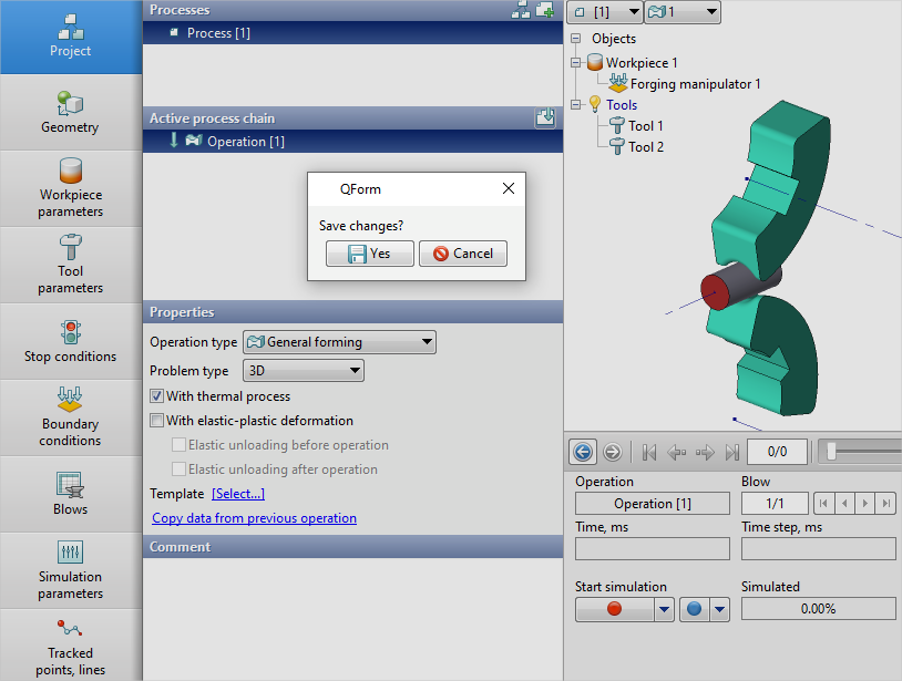
12.Click on the button Simulation![]() , and the program will ask to save the project. Give the project a name and click yes. After that, the simulation of the first operation will begin.
, and the program will ask to save the project. Give the project a name and click yes. After that, the simulation of the first operation will begin.
13.When simulation of the operation is finished, open the Project tab and press Add an operation to a chain

14.In the Operation tab select Operation type - General forming, With thermal process, Problem type - 3D. You also need to click on Copy data from previous operation and copy the boundary conditions. Click Forward.

15.In the Geometry tab click Load from file and specify the path to the geometry file reduce_rolling_op2.shl.
The uploaded geometry will appear on screen. Click Forward
16.In the Workpiece parameters tab all remains unchanged. Material, Temperature and Accumulated strain inherited from the previous operation. Click Forward
17.In the Tool parameters tab set all as for the first operation. Click Forward
18.In the Stop conditions tab you need to set the rotation angle Tool 1 regarding own Axis 1 (45˚). Click Forward
19.In the Boundary conditions tab all remains unchanged. Click Forward
20.In the Blows tab you need to set Rotation angle (90˚). Click OK

21.Click on the button Simulation ![]() , and the program will prompt save the project. Save the project by clicking yes. After that, the simulation of the second operation will begin.
, and the program will prompt save the project. Save the project by clicking yes. After that, the simulation of the second operation will begin.