The following sections are available in the main menu:
![]()
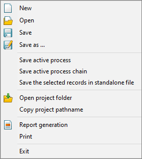
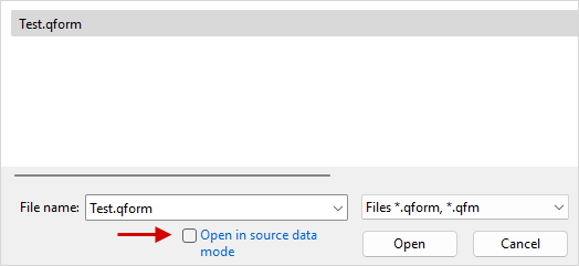
Create – create a new project. Open – open an existing project. When opening a project, there is an additional option to start in source data mode, which allows you to open the project at the zero step of the simulation:
Save - save the project. Save as... – save the project with a new name. Save active process – save the selected process in a separate qform-project with or without simulation results . Save active chain – save the selected chain of the operations in a separate qform-project with or without simulation results . Save the selected records in standalone file – save the simulation results to the file only for the necessary records. The command can be used to reduce the size of the transmitted data, for example, when sending a request to the technical support. Open project folder – open the project directory in the Windows file manager. The shortcut key is F12. Copy project pathname- copy to the clipboard the path of the opened *.qform file . Report generation – open a window in which the paths to the report template and the file of the generated report are specified, and the generation of the technical report is carried out. Print - print the simulation results . Exit – close the program |
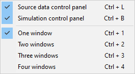
In this tab, you can hide or show Initial data panellocated on the left part of the software window, and simulation control panellocated at the bottom of the software window. You can also select the amount of windows when work in multi-window mode. |
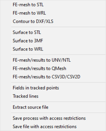
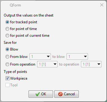
Export to STL/DXF/XLS – save 3D or 2D geometry of the selected simulation objects at any simulation step, respectively, to files with the extension *.stl (3D simulation) or *.dxf (2D simulation). When 2D workpiece geometry is exported to a *.dxf- file, all flow lines and points are exported too. It is possible to export the coordinates of surface nodes of 2D objects or surface nodes of a cross cut plane of 3D objects to file with the *.xls extension. Export to 3MF – save the simulation results, including the geometry of objects and calculated fields, to a file with the extension *.3mf, which can also be used for color 3D print. Export to WRL – save the simulation results , including the geometry of objects and calculated fields, to a file with the extension *.wrl, which can also be used for color 3D print. Export mesh to UNV/NTL – save the finite element mesh of the selected object for the active record of the simulation to a file with the *.unv or *.ntl extension. Export to QMesh – save mesh of selected objects, as well as calculated fields of temperatures, plastic deformations, stress fields, fields of elastic-plastic simulation to a file with the *.qmesh extension. The saved *.qmesh file can be imported into other qform-projects. Fields at traced points – save the field values in the traced points in Excel- file or in *.npz ( only for option for tracked point) . The type of the saved file can be selected in the File type field in the save window . First, there are three options for output values on the sheet: •for tracked point - save all fields for all specified points. In this case, a separate one is created for each point. Sheet in Excel file or an *.npz file is generated containing NumPy arrays for the fields of each point. •for point of time - save the values of all fields for all specified points. In this case, for each recorded time increment, a separate Sheet in an Excel- file will be created. •for point of current time - save the values of all fields for all specified points to a file only for active calculation recording. Secondly, there are three saving options for blows or operations: •Blow - the values for the current blow are saved in the current operation. •From blow to blow - the values in the interval of selected blows in the current operation are saved. •From operation to operation - values are saved in the interval of selected operations in the current process.
Export flow lines – save flow lines to a file with the *.iges extension Bearing contour to DXF – auxiliary module command Extrusion. See the documentation QForm UK Extrusion. Profile Cross cut plane in CSV2D/DXF – auxiliary module command Extrusion. See the documentation QForm UK Extrusion. Export to CSV3D/CSV2D - *.csv format containing the coordinates of the finite element mesh nodes and the value of the calculated fields in these nodes. Traces data – auxiliary module command Extrusion. See the documentation QForm UK Extrusion. Extract source file – save the initial geometry of the selected object to a file. |
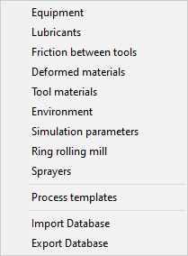
In this section , you can open theequipment, lubricants, friction conditions between tools, deformed materials, tool materials, environments, simulation parameters, ring rolling mills and sprayers database. Process templates- opens a database of operation parameters, in which workpiece and tool parameters, calculation parameters, as well as parameters of special processes are set. database import command: Import database- unpack into the user database specified in the explorer *.zip-archive containing the previously exported database. Export database– save the current user database in *.zip-archive. |
Some auxiliary commands are available in this tab: Truncate results after current record – delete all calculated operation records following the selected record. |
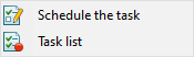
Schedule the task – add an active chain, an active process or the whole project to the specified task list, which can be launched for simulation using Task Manager. Task list - run Task Manager. |
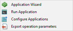
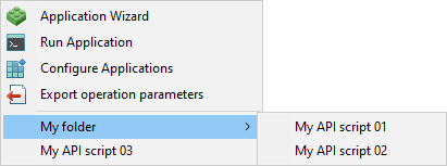
Application Wizard - run the App Wizard application, containing all available API commands and their parameters. App Wizard also allows you to execute commands, create commands sequences, save and load commands sequences, and convert command code to any programming language available in App Wizard. Run Application – run an existing software. Configure Applications - allows you to specify the path to the user software to add it to the Applications tab for a quick call.
Export operation parameters - creates a *.scm-script that allows you to recreate an active operation with the help of the Run Application command. The script Name is in the format <FILENAME> <PROCESS NAME> <OPERATION NAME>.scm. It also extract all the necessary files used by the script to the appropriate folder *.resources. |
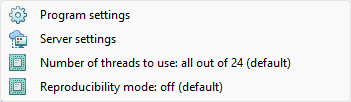
Program settings – open the general settings window QForm UK. Server settings – open the calculation server options window. Required when work in the Client Server or in the QForm UK Cloud software. Number of threads to use - select how many threads will be used in the simulation. Reproducibility mode - allows you to enable the mode of reproducibility of simulation results. |
Help – open the user manual QForm UK. HelpQForm UK Extrusion - open the QForm UK Extrusion user manual. License – open the license window. About QForm – show QForm UK version. |