There are two types of simulation in QForm UK:
1. Main simulation – simulation of forming processes or heat treatment.
2. Post-processing mode simulation after the Main simulation: tool simulation, tracking the lines, points and execution of subroutines.
| The data structure of project QForm UK |
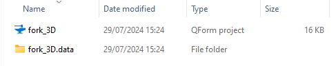
After saving the project file [file name].qform in the specified directory the folder [file name].data will be created in the same directory. File [file name].qform contains all the initial data necessary for the simulation. Directory [file name ].data contains several files with the simulation results and tracking information. For example, for the project fork_3D.qform the program will automatically create the directory fork_3D.data.
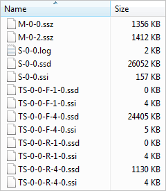
The directory fork_3D.data contains the following files:
*.ssz files contain the initial mesh of the corresponding tools. *.ssd files contain the results of the simulation into the nodes of the finite element mesh and tracking information. *.ssi files contain indexes of the data respectively stored in the *.ssd files. *.log files contain reference text information about the simulation. *.stat files contain information about the number of the current operation and service information about simulation files. File view contains information about the properties of the created section planes. |
After the initial data preparation project simulation may be run by clicking the Simulation button
When the simulation starts, the button Simulation
|


To simulate tools in the Post-processing mode, all simulated tools must have pre-defined boundary conditions applied in the SourcedatapanelBoundaryconditions tab. After the Main simulation you have to select the desired simulation record and press the button Simulate tools independently:
After selecting the tools to be simulated and clicking the button Simulation the program performs simulation of tools for active time step of the Main simulation. The distribution of the effective stress in the tools for selected simulation record is shown below. Records on which the tool simulation has been completed are marked with blue vertical lines:
|


Tracing of points and lines for workpiece is performed in the Post-processing mode after the Main simulation. Points and lines can be created at any simulation step in the SourcedatapanelTracked points, lines tab. The program will automatically track created points and lines by clicking Execute tracking for the operation The program will automatically track created points and lines by clicking Execute tracking for whole chain
|


Subroutines execution for workpiece is performed in the Post-processing mode after the Main simulation. Subroutines can be added in the Initial data panelSubroutines tab. Subroutines execution for active operation or blow is started by clicking Execute subroutines Subroutine execution for active operation and for all subsequent operations of the active process chain is started by clicking Execute subroutines for whole chain
|


See also: