Some tools for displaying results are discussed in details in this chapter.
To analyze the filling of a die cavity several tools are available: 1.Displaying the contact area (button 2.Displaying the contact nodes (button 3.Displaying the Distance to contact field (available in the field list). Shows the current distance to the tool surface as a field.
|


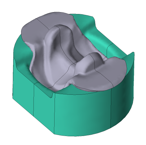
In cases of process simulation with specified symmetry planes, it is possible to display the full view of objects (button
|
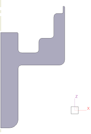
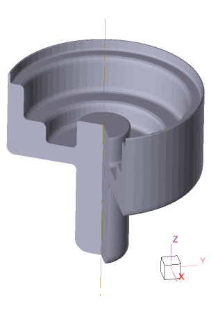
It is possible to display a three-dimensional view of objects, when simulating two-dimensional tasks (button
|
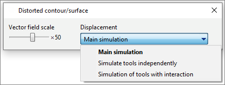
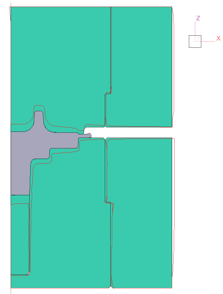
It is possible to display the distorted contour with a user defined scale (button
It is necessary to select the type of the tool simulation in the Displacement drop-down menu: •Main simulation - if you activate the coupled tools simulation; •Simulate tools independently or simulation of tools with interaction - are used if the tool simulation was performed after the main simulation.
|
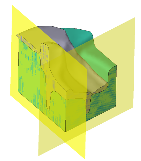
The Minimum distance to surface field can be used to analyze metal flow defects related to the inward drawing of metal from the surface. Sequence of actions for work with the field: 1.Go to the last simulation step; 2.Change the maximum scale value by the size of the studied near-surface layer. First of all, this value depends on the dimensions of the workpiece; 3.Make sure that the field is parallel to the final form of the workpiece surface. Use the Add section plane command to analyze the fields in different parts of the forging when simulating a 3D tasks; 4.In case of detection of places where the fields is drawn inward from the surface of the workpiece, it is recommended to additionally investigate the flow of metal with the help of an array of tracked lines and tracked undersurface flow lines.
The principle of work of the field is shown below using the example of the movement of two tracking points. At the beginning of the process, one of the points is close to the surface of the workpiece, the other is further away. At the end of the deformation process, both points move deeper into the workpiece:
|
||||||||||

