Module Reverse rolling is designed to simulate reverse rolling processes. To activate the module you need to select Operation type - Reverse rolling. The module is adapted for reverse rolling and allows you to simulate processes with two and three horizontal rolls.
|
|


Preparation of initial data
When working in the reverse rolling module, the Passes tab is available on the initial data panel, in which the initial data is prepared for a user defined passes count. The revolutions of the tools are also set here. In the tab Rolling parameters the feature Three high mill stand is available for simulation a process with three horizontal rolls. The preparation of the remaining initial data is carried out similarly to the preparation in the module Longitudinal rolling.
The tab Passes is a table with a set of parameters for passes. The number of passes for one operation is set using the passes table. For the pass it is possible to specify:
•Time of preliminary cooling in air;
•Workpiece crosswise movement;
•Workpiece rotation angle;
•Rolling gap change;
•Upper and lower tool rotational speed;
•Side tool rotational speed;
•Upper tool crosswise movement;
•Workpiece vertical movement (available when activated Three high mill stand in Rolling parameters);

Controlling the passes count
In the table of passes, each pass has a line with the corresponding pass number. By default there is only one pass:on the tab Passes:
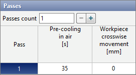
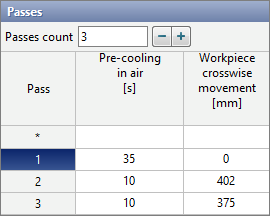
It is possible to control the passes count by directly entering the required number of passes manually, or using help buttons – And +.
|
Information |
If there is more than one passes, a line with an index * appears at the origin . Specifying a value for any parameter on this line applies that same value to all passes. |
|
Passes parameters
In the passes table, each parameter has a corresponding column with the corresponding name. On the tab Passes, the following columns are always available: Pre-cooling in air, Rolling gap change, Upper tool rotational speed, Lower tool rotational speed, Side tool rotational speed, and Upper tool crosswise movement. If certain conditions are met, then advanced columns appear: Workpiece crosswise movement, Workpiece rotation angle, Workpiece vertical movement.
•Pre-cooling in air- parameter, designed for simulation of the cooling of workpieces in the environment before a pass for a specified time. It can be used to simulate cooling during transporting from a heating furnace or cooling during moving of workpieces between passes. Simulation of such cooling occurs at the zero step of the pass after starting the simulation. Cooling is carried out in the environment without taking into account contact with the tool.
|
Information |
Even though the parameter is called Pre-cooling in air, cooling will be carried out in accordance with the parameters of the fit specified in the line Environment on the tab Boundary conditions. |
|
•Workpiece crosswise movement - parameter, designed for positioning the workpieces along the tool axes. The workpiece will move at the zero pass step after the simulation starts. Displacement is carried out to a specified distance along the axes of the upper and lower tools. If the tools axes are parallel to the global coordinate axes OX, then with a positive value of the parameter the workpiece will move in the positive direction of the OX axes, and with a negative value - in the negative direction of the OX axes. If the tools axes are parallel to the global coordinate axes OY, then the workpieces displacement in the same way along the OY axes .
|
A - direction of positive displacement of the workpieces. The tools axes are parallel to the global coordinate axes OX. |

|
Information |
Parameter Workpiece crosswise movement is available if the workpieces has a specified axis. |
|
•Workpiece rotation angle - parameter, designed for rotation the workpieces around its axes. The rotation is carried out at the zero step of the pass after starting the simulation. A positive value corresponds to counterclockwise rotation around axis, a negative value corresponds to clockwise rotation around axis (see section Blows)
|
Information |
Parameter Workpiece rotation angle is available at a given axes for the workpieces. |
|
•Rolling gap changeis a parameter for the movement of the upper tool along the global OZ coordinate axis. The displacement is carried out at the zero step of the pass after the start of the simulation. A negative value moves the upper tool downward, and a positive value moves it upward.
|
A - direction of rolling gap change. If the parameter value is negative, the upper tool is moved down, if it is positive, the upper tool is moved up. |

•Upper tool rotational speed and Lower tool rotational speed are parameters designed to set the rotation speeds of the horizontal rolls of the current pass.
•Side tool rotational speed – parameter, designed to set the rotational speed of the side (vertical) rolls of the current pass.
|
A - upper roll; B - lower roll; C - side rolls. |

•Upper tool crosswise movement - parameter, designed to displacement the upper tool along its axes. The displacement is carried out at the zero step of the pass after the start of the simulation. If the axis of the upper tool is parallel to the global coordinate axes OX, then with a positive value of the parameter the upper tool will move in the positive direction of the OX axes, and with a negative value - in the negative direction of the OX axes. If the axis of the upper tool is parallel to the global coordinate axes OY, then the displacement is carried out in a similar way along the OY axes.
|
A - direction of positive upper tool crosswise movement |

•Workpiece vertical movement - parameter, designed to displacement the workpieces vertically when simulation a reverse rolling process with three horizontal rolls. To enable the functionality, go to the tab Rolling parameters and activate the feature Three high mill stand:

The displacement is carried out at the zero step of the pass after the start of the simulation. A negative value corresponds to the displacement of the workpieces in a negative direction along the global coordinate axes OZ, a positive value - the displacement of the workpieces in a positive direction along the OZ axes.
|
A - direction of negative vertical displacement of the workpieces; B - direction of positive vertical displacement of the workpieces. |

QForm UKautomatically determines for the current pass which tool is the upper one and which is the lower one.
|
Information |
Parameter Workpiece vertical movement is available if in Rolling parameters the featureThree high mill stand is enabled and for the workpieces it is specified axis. |
|
Working with the table of passes in third-party applications
The table of passes can be imported or exported using files *.xlsx and *.xls. Export and import are carried out by commands located at the top of the tab Passes:

Below is the structure of the passes table exported from QForm UK in Microsoft Excel:

A table prepared in Microsoft Excel for import into QForm UK.
Viewing simulation results for a reverse rolling operation
Switching between passes can be done in two ways: using arrows Switching between passes on simulation control panel or by clicking on the pass number in the passes table. Switching is only possible for simulated passes. Depending on the state of the pass, the pass number in the table will have a different background - a gray background means that the pass has not been simulated, a dark blue background means an active pass, a blue background means that the pass simulated:
