There are two tool simulation types in QForm UK:
•in Postprocessor mode, after the shape change simulation of the workpiece
•in Coupled deformation task mode, when the stress-strain state of the tool is calculated during the simulation process of the workpiece shape change.
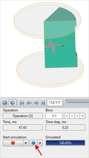
Below considered the tool simulation in the Postprocessor mode in Operation 3 of QExample case.
Select the simulation step that corresponds to the maximum load on the tool. To do this, click the button Graphs![]() and graph the function Load(Time) for Tool 1. Exactly for this step it is reasonable to perform the tool simulation:
and graph the function Load(Time) for Tool 1. Exactly for this step it is reasonable to perform the tool simulation:

To implement tool simulation, it requires to set rigid fixing of tool in the tab Boundary conditions. Highlight Tool 1, and a list of boundary conditions will appear below. Click Rigid fixing:

Select the domain shape, for example, Cylinder:

Enter the dimensions of the cylinder domain manually or using the tool Dimensions alteration mode![]() , then using the tool Positioning
, then using the tool Positioning![]() move the created domain to intersect the fixed part of the tool. Click Done:
move the created domain to intersect the fixed part of the tool. Click Done:

Similarly, set the rigid fixing for Tool2.
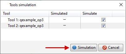
Click the button Tools simulation:
In appeared window toolssimulation, press the button Simulation:
QForm UK will suggest to save the changes. Click yes.
After that, the tools simulation will be done, a vertical blue dash will appear on the selected simulation step in the results scroll field![]() , and in the tab Tool fields the calculated fields will be displayed. Activate, for example, Effective stress:
, and in the tab Tool fields the calculated fields will be displayed. Activate, for example, Effective stress:

Comparing the value of effective stress with the yield stress of the tool material, it's possible to estimate the probability of plastic deformation.
To show the displacement along oz select Displacement Z, as in the picture below. Need to pay the attention that the upper tool and the workpiece are hidden, the symmetry display of the tool is active using the button Symmetry![]() on the tool bar and the edges are hidden limiting the symmetry using the button Show/hide edges
on the tool bar and the edges are hidden limiting the symmetry using the button Show/hide edges![]() :
:

See also:
Coupled deformation task 2D-3D