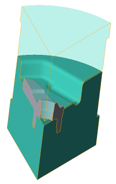
The Task consists of three operations: upsetting, preforming and final forging. 2D axisymmetric task is solved during the first operation simulation. For the second and third operation simulation - a 3D task with two symmetry planes is used. At the end of the third operation - the final forging - the flash is cut off and the hole is punched.
Operation 1 |
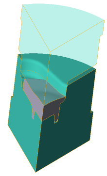
Operation 2 |
Operation 3 |
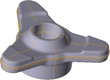
The final forging |
|---|---|---|---|
|
|
|
|
Initial data
Operation 1 |
||
Operation |
Process type |
General forming with thermal processes consideration |
Problem type |
2D axisymmetric |
|
Geometry |
Load from file |
qexample_op1.crs |
Workpiece parameters |
Material |
Steel C45 (1-0503) (Standard: File name) |
Temperature |
1200˚С |
|
Tool parameters |
Drive |
Tool 1 - Mechanical press 10 MN Tool 2 - Fixed drive +OZ |
Lubricant |
Tool 1, 2 - Graphite-water (Hot forging/Steels/Graphite + Water) |
|
Material |
Tool 1, 2 - L6 HRC42 (Standard: File name) |
|
Temperature |
Tool 1, 2 - 200˚С |
|
Coupled deformation |
Not |
|
Heat transfer to workpiece |
Simple |
|
Stop conditions |
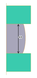
Distance |
48 mm between Tool 1 and Tool 2 |
Boundary conditions |
Environment |
Air 20˚C |
Blows |
Number of blows |
1 |
Cooling in air |
5 sec |
|
Cooling on tool |
2 sec |
|
Simulation parameters |
|
Default |
Operation 2 |
||
Operation |
Process type |
General forming with thermal processes consideration |
Problem type |
3D |
|
Geometry |
Load from file |
qexample_op2.shl |
Workpiece parameters |
Material |
Inherited from previous operation |
Temperature |
Inherited from previous operation |
|
Tool parameters |
Drive |
Tool 1 - Mechanical press 10 MN Tool 2 - Fixed drive +OZ |
Lubricant |
Tool 1, 2 - Graphite-water (Hot forging/Steels/Graphite + Water) |
|
Material |
Tool 1, 2 - L6 HRC42 (Standard: File name) |
|
Temperature |
Tool 1, 2 - 200˚С |
|
Coupled deformation |
Not |
|
Heat transfer to workpiece |
Simple |
|
Stop conditions |
Distance |
16 mm between Tool 1 and Tool 2 |
At point |
x=30, y=40, z=40 |
|
Boundary conditions |
Environment |
Air 20˚C |
Blows |
Number of blows |
1 |
Cooling in air |
3 sec |
|
Cooling on tool |
2 sec |
|
Simulation parameters |
|
Default |
Operation 3 |
||
Operation |
Process type |
General forming with thermal processes consideration |
Problem type |
3D |
|
Geometry |
Load from file |
qexample_op3.shl, qexample_op3_trim_surface.shl |
Workpiece parameters |
Material |
Inherited from previous operation |
Temperature |
Inherited from previous operation |
|
Tool parameters |
Drive |
Tool 1 - Mechanical press 10 MN Tool 2 - Fixed drive +OZ |
Lubricant |
Tool 1, 2 - Graphite-water (Hot forging/Steels/Graphite + Water) |
|
Material |
Tool 1, 2 - L6 HRC42 (Standard: File name) |
|
Temperature |
Tool 1, 2 - 200˚С |
|
Coupled deformation |
Not |
|
Heat transfer to workpiece |
Simple |
|
Stop conditions |
Distance |
2 mm between Tool 1 and Tool 2 |
Boundary conditions |
Environment |
Air 20˚C |
Blows |
Number of blows |
1 |
Cooling in air |
3 sec |
|
Cooling on tool |
2 sec |
|
Simulation parameters |
|
Default |
1.To create the first step operation (upsetting) click Create a new process

2.In the tab Operation select the Operation type - General forming, the Problem type - 2D axisymmetric. Click Forward

3.In the tab Geometry click Load from file(2D) and specify the path to the geometry file C:\QForm UK\12.0.1\geometry\qexample\qexample_op1.crs. The uploaded geometry will appear on screen. Click Forward

4.In the Workpiece parameters tab you need to set the material and workpiece temperature. Click in front of Material[Select...].
Select the material Steels\Carbon steels\C45 (1-0503)in the opened database window (Standard: File name) and double click on it, the material will appear in the tab Workpiece parametersafter that

Set the workpiece temperature to 1200˚C. Click Forward

5.In the tab Tool parameters the drive type, temperature and lubricant must be select for each tool. To be noted that in this example Tool 1 - upper tool, and Tool 2 - bottom tool. Opposite Drive-Tool 1 click [Select...], and the equipment database window will be opened. Choose equipment Standard\Mechanical press\10MN and double click on it, the selected drive will appear in front of Drive- Tool 1after that

Tool 2 - fixed and it works in the direction of the axes OZ. In front of Drive-Tool 2 click [Select...], in the equipment database window, select Fixed drives\+OZ drives and double click on it, the selected drive will appear in front of Drive-Tool 2
In front of Lubricant click [Select...] and double click to set the lubricant Hot forging/Steels/Graphite + Water. Lubricant will appear immediately for all tools.
In front of Material click [Select...] and double click to set the material L6HRC42 (Standard: File name). The Material will appear immediately for all tools.
In front of Temperature enter200˚С. The Temperature will be specified for all tools. Click Forward

6.In the Stop conditions tab you should set final distance between the tools. Click Add condition.
Opposite Condition 1 select Distance. Specify the value of the final distance (48 mm) after that and select the tools between which it is set. Click Forward

7.In the Boundary conditions tab all remains unchanged. Click Forward

8.In the Blows tab set the cooling in air and in the tool. Click Forward

9.In the tab Process parameters everything remains unchanged. Click Finish.
10.Click the button Simulation ![]() and the program will suggest to save the project. Enter the project a name and click OK. The simulation will start after that.
and the program will suggest to save the project. Enter the project a name and click OK. The simulation will start after that.
11.When the simulation is completed, in the tab Project select Operation 1. To create the second step in the chain, click the icon Addoperationinchain

12.In the tab Operation select Operation type - General forming, Problem type - 3D. Click Forward
13.In the tab Geometry click Load from file and specify the path to the geometry file C:\QForm UK\12.0.1\geometry\qexample_op2.shl. The loaded geometry will appear on screen. The 2D geometry of the upset workpiece is inherited from the first operation. Click Forward

14.In the Workpiece parameters tab all remains unchanged. Material, shape of workpiece , temperature , and accumulated strain are inherited from the previous operation. Click Forward.
15.In the tab Tool parameters the drive type, temperature and lubricant must be select for each tool. Follow the same steps as for the first transition. Click Forward.
16.In the Stop conditions tab you should set final distance between the tools. Enter an final distance of 16 mm at point with coordinates X=30 mm; Y= mm; Z=40 mm. Click Forward

17.In the Boundary conditions tab all remains unchanged. Click Forward.
18.In the Blows tab set the cooling in air and in the tool. Click Forward.
19.In the tab Process parameters everything remains unchanged. Click Done.
20.Click the button Simulation![]() , and simulation of the second transition will start.
, and simulation of the second transition will start.
21.When the simulation is completed, in the tab Project highlight Operation 2. To create the third step in the chain, click on the icon Add operationinchain.
22.In the tab Operation click Copydatafrompreviousoperation. In the new open window, click OK. All the original data, including the tool geometry, is now completely copied from the previous operation. Click Forward

23.In the tab Geometry click Load from file and specify the path to the geometry file qexample_op3.shl. A window will appear with the message "An Object with the same name already exists ". Check the box Rememberchoice and click Overwrite. The loaded geometry will appear on screen

24.Click again on Load from file and specify the path to the geometry file qexample_op3_trim_surface.shl. This file contains the clipping surface geometry . The flash is cut off at the end of the operation and a hole is punched, so it is necessary to assign the properties of the clipping surface: Cuttingway - Outsideclipping surface and Aftercurrent operation. Click Forward

25.In the Workpiece parameters tab all remains unchanged. Material, shape of workpiece , temperature , and accumulated strain are inherited from the previous operation. Click Forward.
26.In the tab Tool parameters all remains unchanged, all data is copied from the previous operation. Click Forward.
27.In the tab Stop conditions it is necessary to change the final distance between the tools. Enter a final distance 2 mm and uncheck the distance measurements at a given point. In this operation , this point is determined automatically. Click Forward.
28.In the tab Boundary conditions all remains unchanged. Click Forward.
29.In the tab Blowsall remains unchanged, all data is copied from the previous operation. Click Forward.
30.In the tab Process parameters all remains unchanged. Click OK.
31.Click on the button Simulation![]() , and the simulation of the third transition will begin. When the final distance is reached, the hole will be punched and the flash trimmed.
, and the simulation of the third transition will begin. When the final distance is reached, the hole will be punched and the flash trimmed.