Forces of contact friction at metal forming depend on many factors: contact pressure, lubricant properties, thickness of lubricant film, temperature, resultant sliding velocity, tool surface finish, mechanical properties of a tool material, properties of deformed workpiece material etc.
At simulation a common practice is to use more simple dependencies taking into account one or two of the above mentioned factors. The impact of other factors is usually reduced to some coefficients obtained from the experiment.
The next three laws are the most common ones: 1.Coulomb law according to which the specific friction force τ is proportional to contact pressure σn with proportionality coefficient called the friction coefficient μ,
2.Siebel's law according to which the specific friction force is proportional to maximum shear stress at sheark with proportionality coefficient called the friction factor m,
Maximum shear stress at shear is determined with the material flow stressσS
Friction factor may vary within the limits of 0≤m≤1 3. Complex friction laws accounting for contact pressure influence In QForm UK two modifications of combined law are used 3.1 Levanov's friction law, in which:
Here b is the experimental coefficient (b = b0=1.25 as recommended by Levanov) 3.2. Hybrid law of friction representing a combination of Coulomb's and Siebel's friction laws. Here Coulomb's law is applicable until the specific friction force exceeds Siebel's friction.
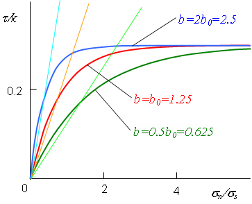
Graphic comparison of different friction laws is shown in figure:
Coulomb's law does not restrict the maximum friction force: the more the normal stresses are, the greater the value of friction force is. In reality at plastic deformation, along with the growth of normal stresses shear contact stresses grow initially almost linearly, and then reaches certain constant value. Theoretical justification of this fact results from Mises plasticity condition. Specific friction forces will be balanced by shear stresses in the deformed material. However, shear stresses cannot exceed the maximum shear stress , which depends on the current value of material flow stress. Therefore, in theory Coulomb's law is applicable only until the specific friction forces reach their maximum value, i.e. for small contact pressure. Thus, Coulomb's law is used for simulation of sheet forming operations, where by contact pressure is usually small. In closed die forging operations contact pressure usually exceeds to a greater extent the flow stress of workpiece material. In this case the use of Coulomb's friction law can cause errors. In reality, friction at surface during plastic deformation is less than the maximum shear stress at shear, because some surfaces are separated by lubricant. We can say that at plastic deformation at the surface of a workpiece contacting with the tool a combination of plastic shear and boundary friction is implemented. The decrease of maximum possible specific friction force for certain contacting surfaces and contact conditions are accounted for by friction factor m. |
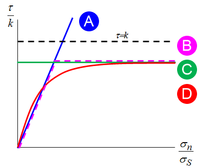
Coulomb's friction force in QForm UK is used for analysis of contact interactions in the assembled tool. For plastic strain analysis QForm UK allows choosing any friction law. The analysis of Levanov's combined law shows that for large values of normal stress ratio to flow stress (σn/σs>4) Levanov's law with a recommended value of coefficient b=1.25 coincides Siebel's law for friction factor m, and for small values (σn/σs<0.5) is close to Coulomb's law with reduced friction coefficient μ≈0.5m. Along with the growth of σn/σs the dependence of friction on contact pressure gradually decreases. QForm UK allows adjusting Levanov's law by setting the value of Levanov's coefficient (by default b=1.25) The graphs of behaviour of shear stress for different values of Levanov's coefficient are shown in figure below.
The reduced coefficient of friction in the initial portion for different values of Levanov's coefficient is determined from the formula
See also: |
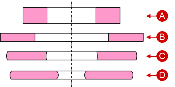
Friction factor value in the QForm UK database is referential. In order to perform the precise analysis it is necessary to correct the value of the friction factor by performing the experimental research. The most common methods for experimental determination of friction factor are the ring compression test (RCT) and double cup extrusion test (DCET). The method of determination of friction factors consists in carrying out the experimental research of the used lubricant for deforming conditions (temperature, pressure, slip velocity, material) close to real ones. After that a series of simulations is performed with different friction factors until the workpiece external shape, deforming force will not coincide with the acceptable accuracy of the experimental data. The RCT method assumes the ring compression with predetermined ratio of initial outer diameter, inner diameter and height. In technical literature [e.g. see T.Altan et al (1986) ] the proportions 6:3:2, 6:3:1, 6:3:0.5 are recommended. The workpiece is compressed for up to 60% and then the value of relative reduction of inner diameter is determined.
Depending on the quality of lubrication, the inner diameter can either enlarge (for good lubrication) or reduce.
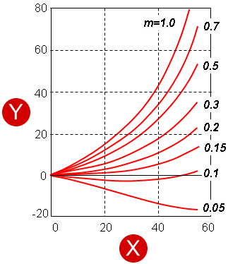
It is possible to use the calibration graphs obtained on the basis of analytic methods as estimated values of friction factors. This figure represents the calibration graphs for ratio 6:3:1 [T.Altan et al (1986)]
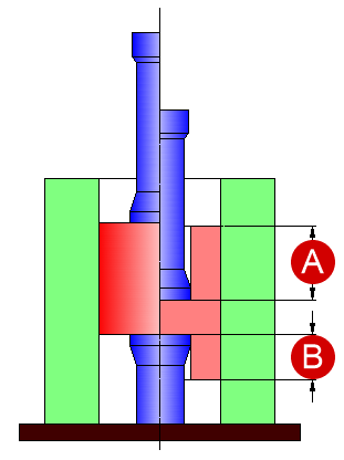
In-depth investigations revealed [for example, see F.Fereshteh-Saniee et al (2004)] that the values of friction factor depend on the properties of the deformed material, test temperature and heat transfer with the tool and environment. That is why the calibration graphs should be obtained by simulation in QForm UK under certain conditions corresponding to the experiment. In the DCET method the relation of obtained cavities depth is determined (principle diagram of the process is shown in figure below). The less the friction is, the closer this relation to the unit will be (in the absence of friction the depth of both cups should be equal).
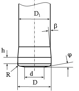
Typical design of extrusion punch
The analysis of different process factors influence on the accuracy of determining the friction factor is described in a study by T.Scharader et al, (2007). The research was carried out for the following tool dimensions: D=15.88 mm, d=9.53 mm, D1=15.72 mm, R=1.17 mm, h=1.57 mm, φ=10°, β =5°. The workpiece dimensions: diameter 31.75 mm, height 31.75 mm. Container diameter is equal to workpiece diameter. However, even this in-depth experimental research does not guarantee the accuracy of friction factor determination, because some real parameters of production processes are not accounted for; besides, friction factor can change during deformation at the expense of the lubrication pressing out and different velocity conditions at the contact surface. Therefore, it is necessary to carry out several variants of simulation by changing the friction factors and Levanov's coefficients within due limits. If the change of the deformed state (external shape of workpiece) and of the graph of deforming force behaviour along the tool path in these variants is minor, then these results are the most reliable. If not, it is necessary to perform extra research. Below an example is shown of friction factor and Levanov's coefficient impact on the workpiece shape obtained during simulation of the swaging operation without lubrication of tube workpiece 3, with thickness 3 mm, height 58 mm, outer diameter 30 mm of aluminium AA1135 (AISI/SAE) / AD1 (GOST/TC) for the same tool pass 1.
The results of a full-scale experiment show that in this case the best approximation is achieved for variant 2 (m=0.4, b=5) |