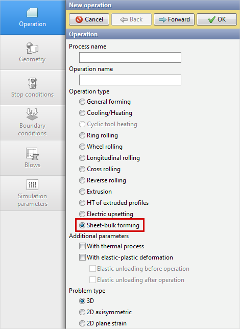
To simulation operations of sheet metal forming in QForm UK a specialized module was created, because 3D simulation of these operation in the basic software module corresponding to the operation type General forming using tetrahedral workpiece meshes is unproductive and generally requires a lot of calculation time due to features of sheet parts, which usually have a thickness significantly less than overall dimensions. To use this module, you need to select the operation type Sheet-bulk forming in the tab Operation when setting simulation source data:
|
|
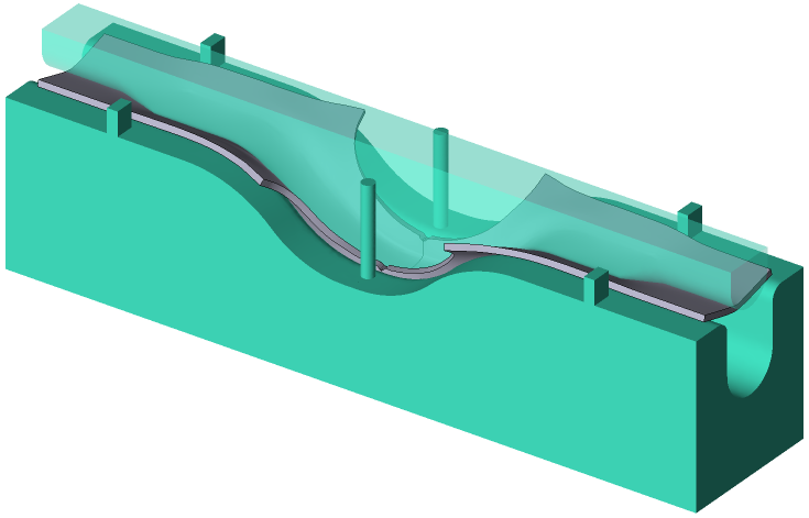
This module implements a special approach based on the features of sheet forming processes. For its correct and predefined working, you must use the problem type 3D and a hexahedral mesh of workpiece structured by thickness.
|
|
|
|
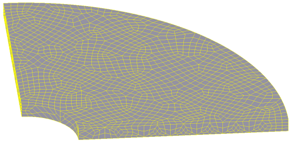
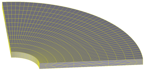
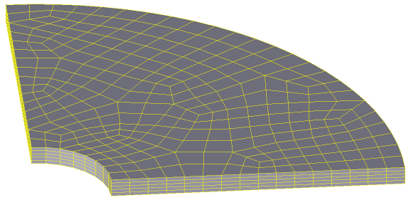
A |
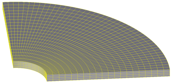
B |
Examples of unstructured (A) and structured (B) by thickness hexahedral meshes of workpiece |
|
Some ways to create hexahedral meshes are given in the section Creating a hexahedral mesh of the manual.
The capabilities of this module include the functionality of the basic software module. For example, it is possible to perform simulations that take into account thermal process and elastic deformations of the workpieces, use spring-loaded tools, etc. Additionally, to expand its capabilities, two standard post-processor subroutines were created. The first one determines the forming limit diagram and the second one determines the thickness of the workpiece during forming. Setting the source data of simulation in the specialised simulation module of sheet forming operations is similar to the basic module. When you use it, there are no additional parameters and tabs in the source data control panel.
When using the specialised simulation module, the following features must be taken into account when preparing source data:
1.In sheet metal forming with bending of the workpiece, the workpiece material is stretched on one side and compressed on the other side in the bending zones during machining. A neutral layer is located between the tensile and compressive zones. When simulating such operations, it is necessary to use workpiece meshes with at least three to five elements per thickness, in order to accurately determine and account for the change in stress-strain state through the workpiece thickness.
2.Because anisotropy has a great influence on the plastic deformation of metal, in simulation of sheet forming of a workpiece produced from orthotropic material with isotropic hardening, it is recommended to use the workpiece material with the Hill-Mises yield criterion in its properties. For example, when simulating the forming of a sheet workpiece that has been cut from a heat untreated rolled sheet.
|
Important |
When preparing the source data for simulation of sheet metal forming of the workpiece for which the Hill-Mises plasticity condition is applied in the material properties, the following requirements for the orientation of the workpiece in space must be observed. The rolling direction of the workpiece must coincide with the X-axis of coordinate system in QForm UK, the direction perpendicular to the rolling direction with the Y-axis, and the thickness with the Z-axis. |
|
3.For hexahedral mesh of the workpiece, the software implements the feature of automatic fragmentation of initial mesh elements at points of contact with tool surfaces. The need of fragmentation and the number of elements into which the original element is divided are determined by the curvature of the contact surface of the tool. So, if in the process of forming a workpiece mesh element begins to contact a non-planar tool surface, and the size of the workpiece element is large for its accurate description, the element is divided into the required number of elements. If after this the fragmented elements begin to contact other tool surfaces of lesser curvature, for which small elements are not required to describe the curvature, they try to return to the original size. This allows to reduce the calculation time by using the initial workpiece mesh from large elements in simulations. Automatic fragmentation of hexahedrons of the original mesh is performed if the option Remeshing during simulation for the workpiece mesh in tab Simulation parameters is activated. The mesh fragmentation process divides not only the element of the surface layer of the mesh, but also elements of all layers through the thickness in case of using the operation type Sheet-bulk forming, or elements of two near-surface layers in case of using other operation types. The number of elements into which the original elements are divided can be controlled using parameter Adaptation factor for the workpiece mesh in tab Simulation parameters. So the number of elements changes directly proportional to the parameter value with the proportionality coefficient equal to 1.
|
Information |
When a hexahedral mesh blank is used, of all the parameters of workpiece mesh in tab Simulation parameters, only Adaptation factor affects the mesh as described above. The other parameters have no effect on the hexahedral mesh of the workpiece! |
|
4.In the current version of the program, for a hexahedral mesh model of the workpiece, a cutting surface can be defined either as a right circular cylinder or as a rectangular parallelepiped created with the Parametric Geometry command in the Geometry tab of the input data panel, or by using a cutting contour in *.dxf format.