Below is an example of simulation rolling in a universal stand using one symmetry planes.
Operation 1 |
|

Initial data
Operation 1 |
||
Operation |
Operation type |
Longitudinal rolling |
Additional parameters |
With thermal process |
|
Problem type |
3D |
|
Geometry |
Load from file |
Tools_and_WP(universal).shl |
Workpiece parameters |
Material |
Steels\Carbon steels\C10; 1.0301 |
Temperature |
1100˚С |
|
Tool parameters |
Drive |
Tool 1, 2 - 62 [rpm] Tool 3 - Free rotation |
Lubricant |
Hot rolling/Siebel m=0.8 |
|
Material |
5140 HRC39 |
|
Temperature |
70˚С |
|
Heat transfer to workpiece |
Constant temperature |
|
Rolling parameters |
|
Default |
Stop conditions |
Time |
2 s |
Boundary conditions |
Environment |
Air 20˚С |
Simulation parameters |
|
Default |
1.Click Create new process
2.In the tab Operation select Operation type - Longitudinal rolling, With thermal process and Problem type - 3D. Click Forward.

3.In the tab Geometry click Load from file and specify the path to the geometry file C:\QForm UK\12.0.1\geometry\rolling\Tools_and__WP(universal).shl. The loaded geometry will appear on screen. Click Forward.

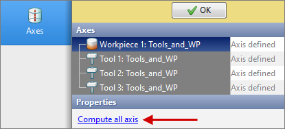
4.In the tab Geometry click Axes, then select all objects and click Compute all axis, click OK. Click Forward.
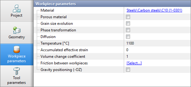
5.In the tab Workpiece parameters it is should be set the material and workpiece temperature. Click next to Material [Select...]
In the database window that opens, select the material Steels\Carbon steels\C10 (1.0301) and double click on it, after that the material will appear in the tabWorkpiece parameters.
Set workpiece temperature 1100˚С. Click Forward.
6.In the tab Tool parameters it is necessary to select the drive, lubricant, temperature, material, heat transfer to workpiece for each tool. For Drive set the rolls rotational speed [rpm] for Tool 1, Tool 2 and free rotation for Tool 3. For this at Tool 1 and Tool 2 select a parameter Constant velocity, then opposite, enter the value 62. For Tool 3 select a parameter Free rotation.
Next to Lubricant click [Select...] and double click to set lubricant Hot rolling/Siebel m=0.8. Lubricant will appear immediately opposite all tools.
Opposite Material click [Select...] and double click to set the material 5140 HRC39. The material will appear immediately for all tools. Next to Temperature set the tool temperature to 70 °C. Next to Heat transfer to workpiece select Constant temperature. Click Forward.

7.In the tab Rolling parameters all remains unchanged. Click Forward.
8.In the tab Stop Conditions, the default setting for rolling modules is Workpiece exit from stand. However, an additional stop condition, such as a process time, must be specified. Click Time. After this, enter the time (2 s). Click Forward .

9.In the tab Boundary conditions all remains unchanged. Click Forward.
10.In the tab Simulation parameters all remains unchanged.. Click OK
11.Click on the button Simulation ![]() , and the programm will offer to save the project. Set the project a name and click Save. The simulation will start after that.
, and the programm will offer to save the project. Set the project a name and click Save. The simulation will start after that.