During sheet forming, the thickness of the workpiece usually changes. The standard post-processor subroutine Thickness can be used to determine thickness values in a calculation performed in the specialised simulation module of sheet forming operations, that corresponds to operation type Sheet-bulk forming, and using a hexahedral mesh of workpiece structured by thickness. This subroutine has one output field thickness, showing thickness values of the workpiece at the active calculation step.
|
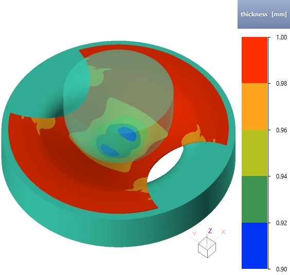
The example with results of determining the workpieces thickness after forming |
For more info about standard post-processor subroutines and their calculation, see the manual section Subroutines.
The thickness in this subroutine is defined as the distance between two nodes of the hexahedral mesh of the workpiece, located on opposite surfaces, which in the initial mesh were on the same straight line parallel to the thickness direction:
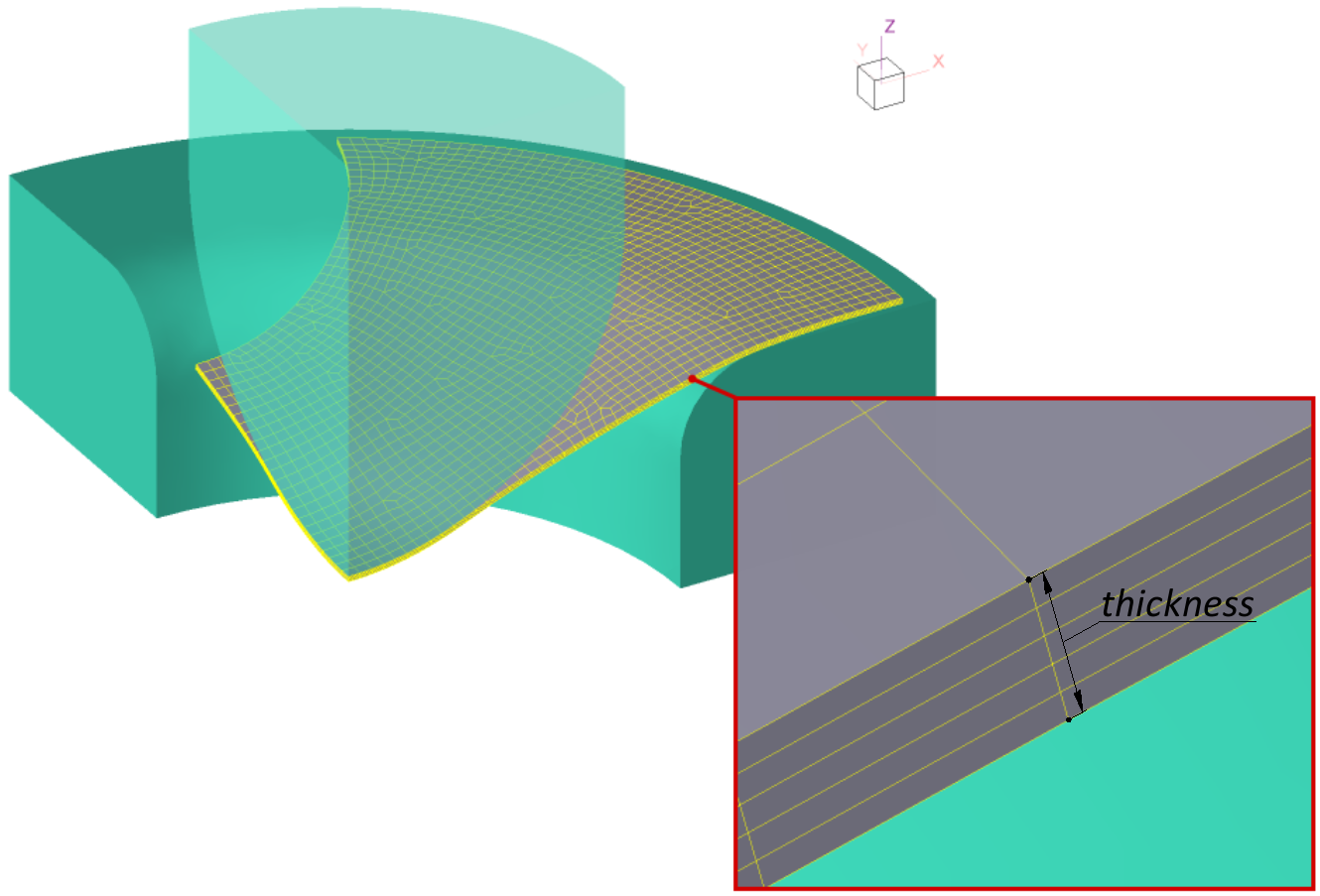
So, if during forming there are places with significant shear deformations in the workpiece, at which the neighbouring layers of the workpiece shift relative to each other and the sides of hexahedrons, initially parallel to the thickness, rotate and deviate from the normal to the surface, the thickness of the workpiece determined with the help of this subroutine will have incorrect values in such places and they should be ignored. In the rest of the workpiece, the defined thickness values will be correct.
|
Information |
The thickness direction for hexahedral workpiece meshes is only determined when using the specialised simulation module of sheet forming operations corresponding to operation type Sheet-bulk forming. In calculations with other types of operation, the thickness direction is not determined and the field thickness calculated by the subroutine Thickness will have zero value. |
|