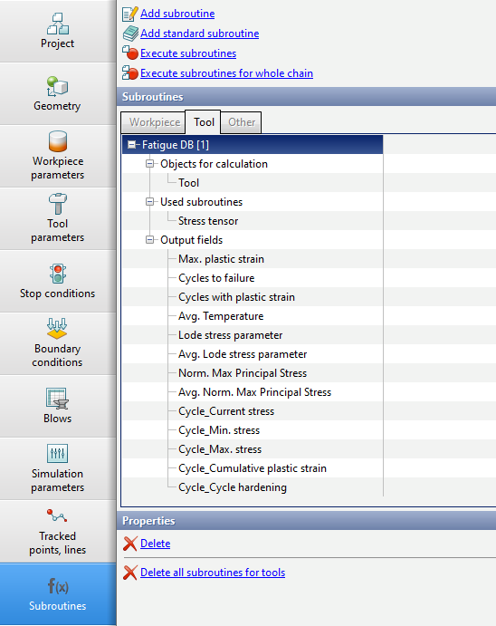
To implement the proposed algorithm in QForm UK a subroutine was created to simulation the durability of dies Fatigue DB. This subroutine allows you to determine the expected amount of cycles before tool failure, taking into account the specified assumptions. Using your own database or user-specified tool materials, you can accuracy estimate the life of tools and the seats where they are most likely to fail. The assessment can be made taking into account the hardening and softening of materials, temperature conditions, various methods for determining the sign of equivalent stresses, etc.
The Subroutine is included in the library of advanced standard subroutines. To simulate Tool Fatigue, first you need to carry out the main simulation of deformation with the included coupled tools simulation, and then simulate the subroutine Fatigue DB in the postprocessor.
|
Information |
To work the subroutine Fatigue DB the feature Tool life must be active in the tool material properties and the necessary parameters are set |
|
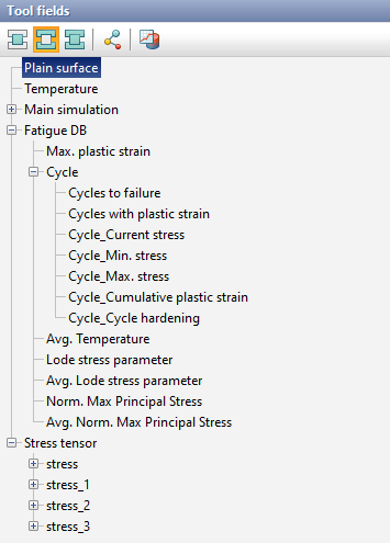
Output fields
Field name |
Dimension |
Short description |
|---|---|---|
Max.plastic strain |
Dimensionless |
Maximum plastic strain per cycle |
Cycles to failure |
Number of cycles |
Predicted amount of cycles before failure |
Cycles with plastic strain |
Number of cycles |
Amount of cycles in which plastic strain occurs (hardening or softening occurs) |
Cycle_Current stress |
Stress |
Equivalent cycle stress |
Cycle_Min. stress |
Stress |
Minimum equivalent cycle stress according to the graph |
Cycle_Max. stress |
Stress |
Maximum equivalent cycle stress according to the graph |
Cycle_Cumulative plastic stress |
Stress |
Accumulated stress per cycle |
Cycle_Cycle hardening |
Stress |
Cumulative hardening (in the case of a positive sign) or softening (in the case of a negative sign) per cycle |
Plastic damage_Failure strain |
Dimensionless |
Failure strain |
Plastic damage_Damage |
Dimensionless |
Damage from plastic strain |
Avg. Temperature |
Temperature |
Average integral temperature value per cycle |
Lode stress parameter |
Dimensionless |
Lode parameter value |
Avg.Lode stress parameter |
Dimensionless |
Average integral value of the Lode parameter |
Norm.Max Principal Stress |
Dimensionless |
Normalized maximum principal stress |
Avg.Norm.Max Principal Stress |
Dimensionless |
Average integral value of the normalized maximum principal stress |
Also when adding a subroutines Fatigue DB automatic added simulation Stress tensor.
|
|
|
Subroutine parameters |
|
Tool output fields |
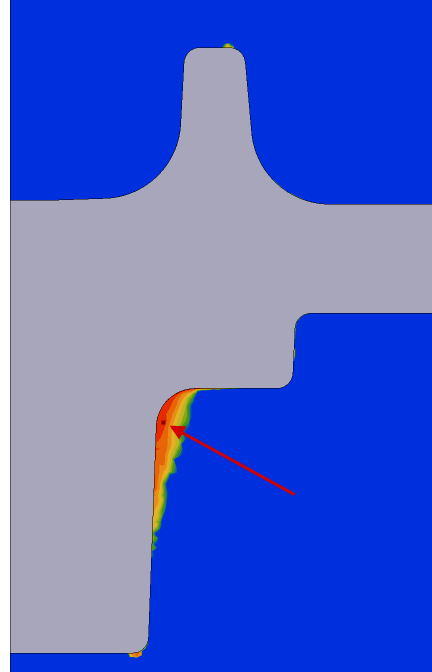
The most important field for research is predicted amount of cycles before failure Cycles to failure. It shows the conditional the amount of cycles, which the tool can work before failure occurs from low-cycle fatigue during elastic-plastic deformation of the tool.
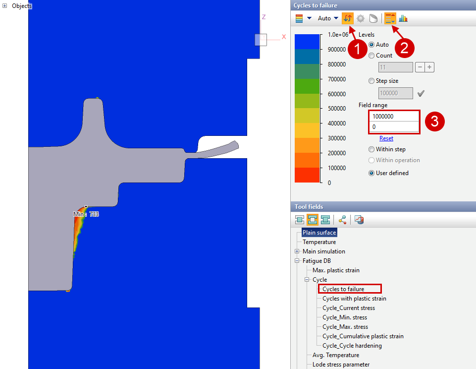
For ease of display, it is recommended to invert the color palette (1), adjust the range of values (3) in order to clearly see problem areas (sequentially changing the maximum field value to 1000, 10000, 100000, etc.). You can also show minimum and maximum value (2)
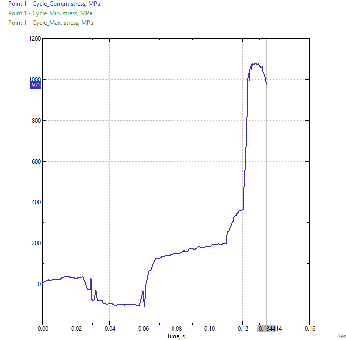
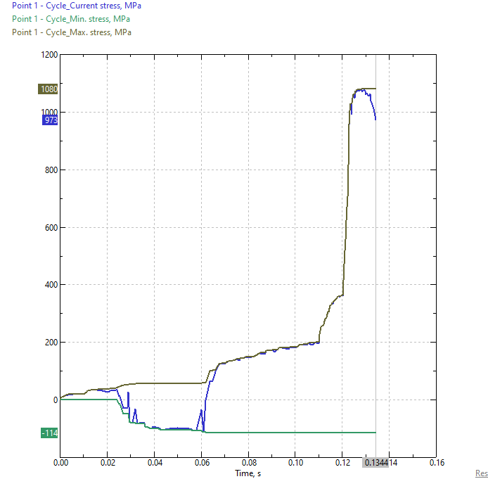
The way these fields Cycle_Current stress, Cycle_Min. stress, Cycle_Max. stress work can be clearly demonstrated if you do Execute Tracking point in the problem domain. At the same time, the graph Maximum equivalent stress will include the maximum value of the equivalent stress graph , which can only increase. Graph Minimum equivalent stress - similarly will include minimum equivalent stress, which can only decrease.
|
|
|
Tracking point |
Graph of equivalent stress at point |
Graphs of the maximum and minimum value equivalent stress values at point |
|
Information |
Stress value Cycle_Min. stress may not necessarily be only negative, similar stress Cycle_Max. stress may not necessarily be only positive. The sign of these stresses depends on the values Cycle_Current stress and graphs of individual points. |
|
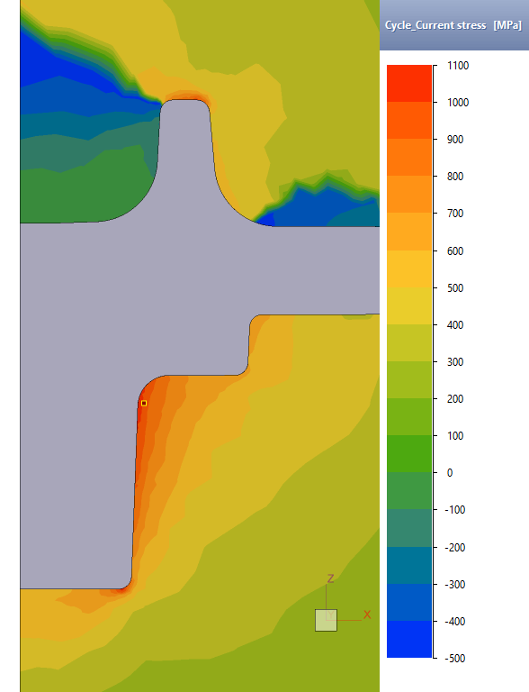
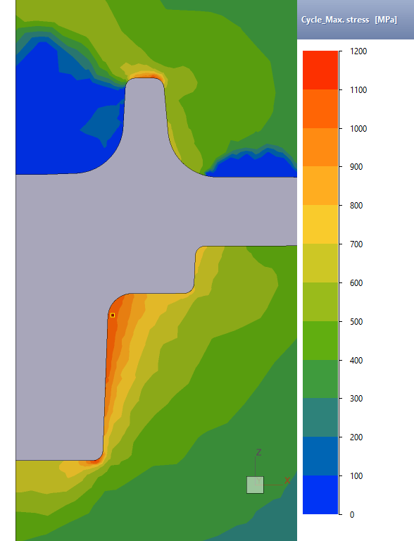
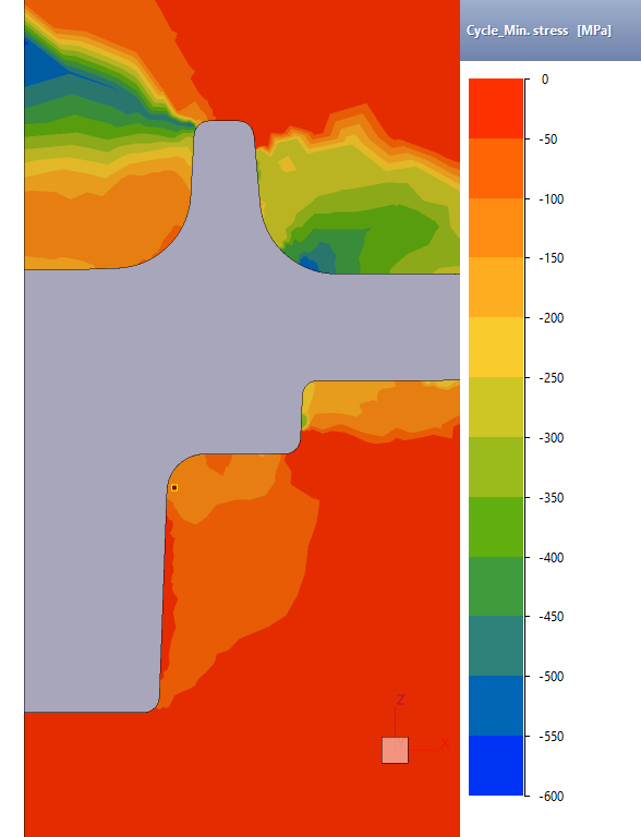
Fields Cycle_Current stress, Cycle_Min. stress, Cycle_Max. stress are useful for for evaluating stress differences and identifying problem seats.
|
|
|
Cycle_Current stress |
Cycle_Max. stress |
Cycle_Min. stress |
Field Lode stress parameter used to analyze the stress state and as an argument to determine Fatigue strength coefficient and Fatigue strength exponent. The Lode parameter is calculated to the formula:
Lode parameter is in the range of values [- 1; 1].
Stress state |
Pure tension (σ1 > 0, σ2 =σ3 = 0) |
Pure compression (σ1 = σ2 = 0; σ3 < 0) |
Pure shear (σ1 > 0; σ2 = 0; σ3= -σ1) |
For the case (σ1 = σ2 = σ3) |
Lode parameter |
- 1 |
1 |
0 |
Doesn't exist |
See also:
Theoretical basis of simulation
Description of fit by parameters and simulation algorithm