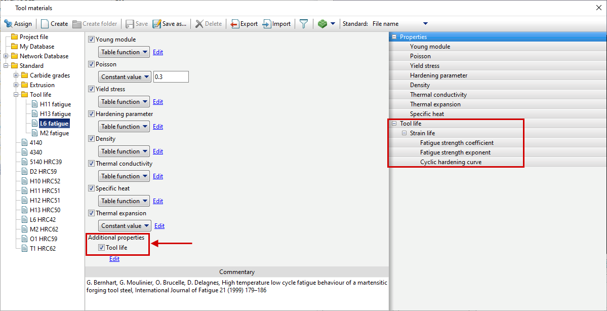
To carry out a fatigue strength simulation, the following parameters must be activated and set in the tool material:
•The additional tool life property is activated. At the same time, a new tab appeared on the right.
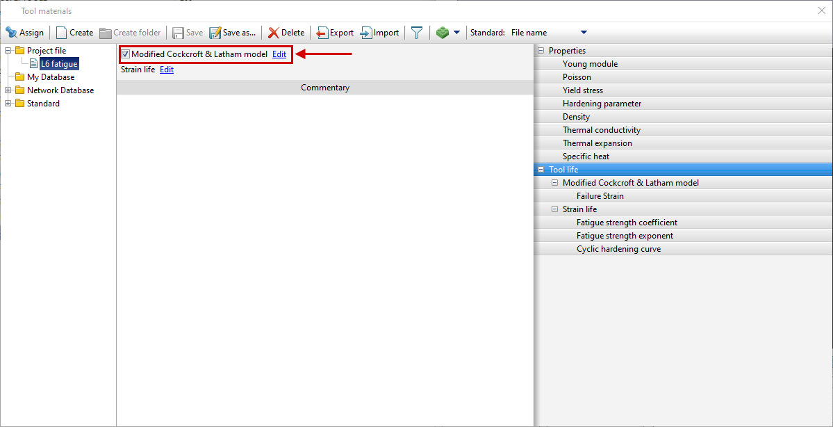
•If necessary, to take into account the modified Cockroft&Latham model, you can activate the corresponding function (in most cases, it is not recommended, since it does not have a significant effect on the results):
|
|
|
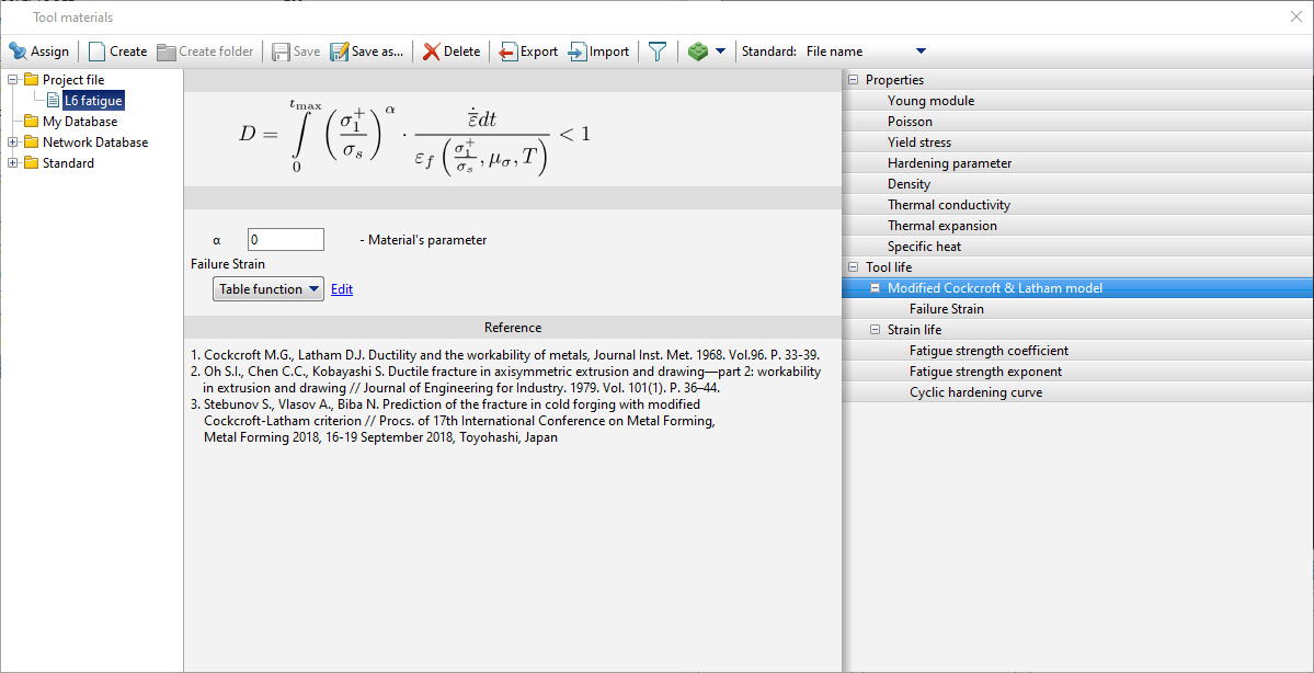
Modification of the Cockroft&Latham model |
|
Model parameters and formula for calculating Cockroft&Latham criterion. |
•The most important parameters of the model are in the Strain life tab
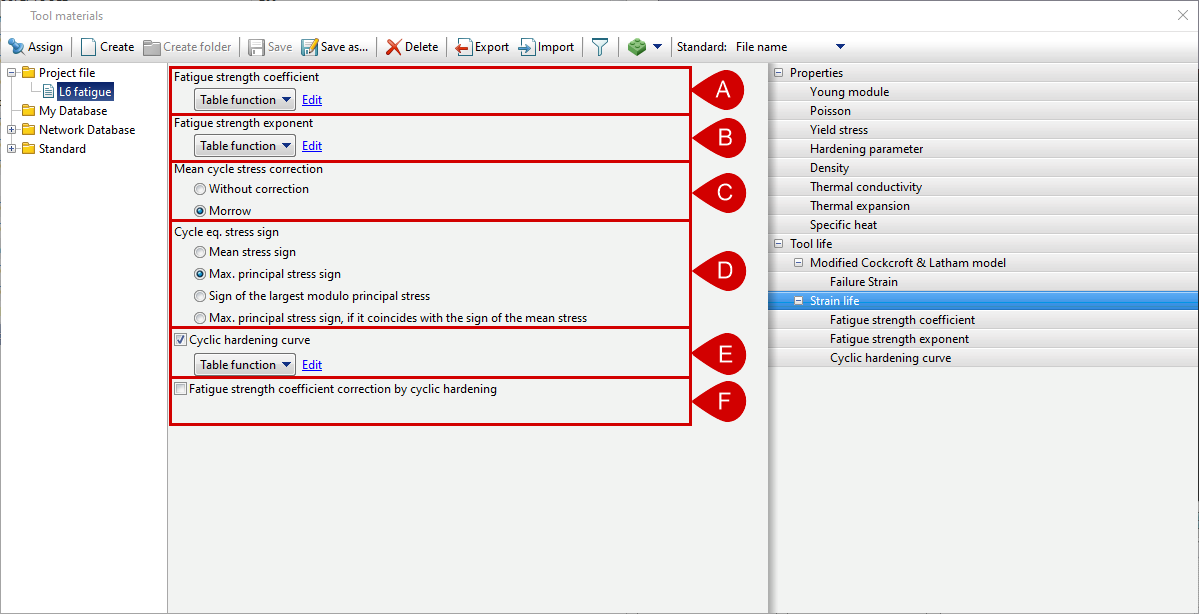
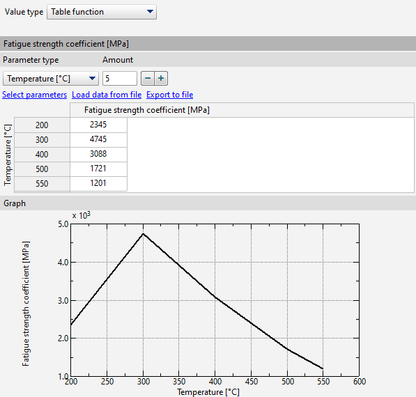
The physical meaning of the coefficient is the true stress at failure under cyclic uniaxial tension. Specified as a constant value or a table function of Temperature, Lode index for stresses, Normalized first principal stress. This coefficient is determined experimentally or selected empirically. Denoted as σ'fin formula (10) Theoretical basis of simulation :
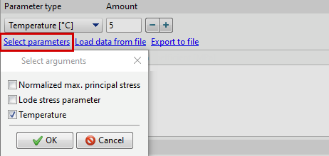
To select arguments, click Select parameters:
|

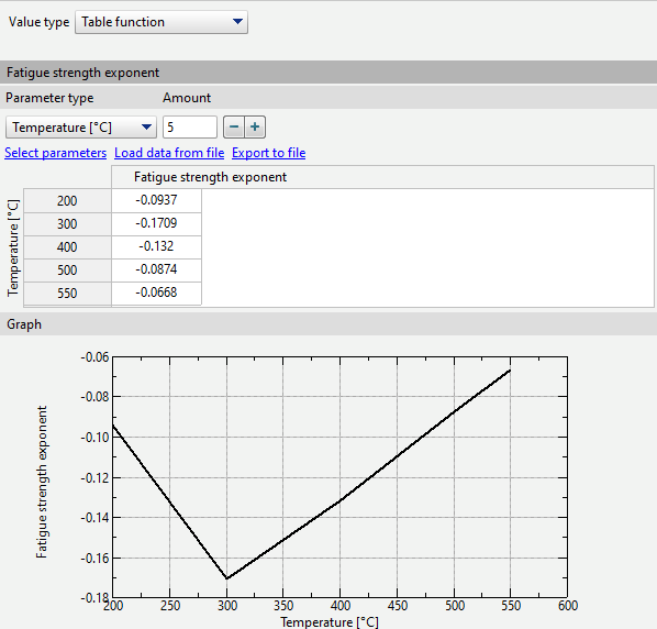
This indicator is defined as the slope of the elastic part of the fatigue curve in double logarithmic coordinates. Specified as a constant value or a table function of Temperature, Lode index for stresses, Normalized first principal stress . The indicator is determined experimentally or selected empirically. Denoted as b in formula (10) Theoretical basis of simulation :
To select arguments, click Select parameters:
|
This parameter allows you to enable or disable correction Morrow σqmto simulation the mean stress in formula. (7) Theoretical basis of simulation
|
Equivalent stress for further computations using formulas (8) Theoretical basis of simulation are defined as equivalent von Mises stress taking into account the sign. The method for determining the sign can be changed to 1 of 4 variants: •Mean stress sign
•Sign of the 1 principal stress
•Sign of the most modular of the principal stress
•The sign of the 1 principal stress, if it coincides with the sign of the mean stress (in case of mismatch, the sign from the previous step is taken)
By default, when creating a new material, the case is activated Sign of the most modular of the principal stress. Changing the way the sign is determined can have a strong impact on the simulation results. In this way, you can control the simulation of fatigue strength and obtain the most adequate result.
|
||||
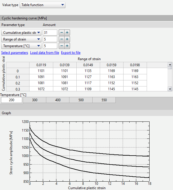
When this parameter is activated, an additional parameter will appear in the formula for simulation the mean stressΔσ (cycle stress amplitude) which allows you to take into account cyclic hardening or softenning. Then, with correction enabled Morrow formula will take the view:
Stress cycle amplitude can be specified by a constant value or a table function. In the second case Stress cycle amplitude is given by curves depending on Cumulative plastic Strain. Curves are plotted for different values Temperature And Range of total strain cycle (difference between maximum and minimum cycle strain ).
|
When this item is activated, the hardening or softenning that occurs as a result of tool strain is added or subtracted from the cyclic strength coefficientσ'f , respectively.. This function only works with a given cyclic hardening curve. Available materials. The database contains 4 pre-made material for work with the subroutine Fatigue DB. The materials are in the standard database folder Tool life: H13 AISI, 1.2344 DIN, 4Х5МФ1С-ЭП572 GOST H11 AISI 1.2343 DIN, 4Х5МФС GOST L6 AISI, 1.2714 DIN, 5ХНМ GOST M2 AISI, 1.3343 DIN, R6M5 GOST In the absence of experimental data for preliminary simulation, you can use the following dependencies using the Roessle-Fatemi hardness method:
HB - Brinell hardness.
•Roessle M. L. and Fatemi A. Strain-controlled fatigue properties of steels and some simple approximations // Ibid. - 2000. - 22. - P. 495 - 511. |
See also: