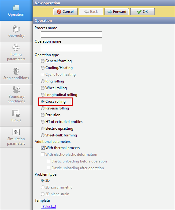
Operation type Cross rolling developed for simulation cross rolling and piercing processes. To activate the module you have to select Operation type - Cross rolling. The operation type takes into account the specifics of the processes and simplifies the setting of boundary conditions for the user.
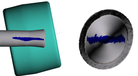
1. Location of strain concentrators Several strain zones are formed and located in the domain of contact between workpiece and the tools in the process of cross rolling. In this regard, we have a number of features for such processes simulation: a) Contact area. Influences the definition of forces and moments. The deformation load is formed by friction tangential to the plain surface of the tools.
b) At every moment, the most part of the workpiece is not deformed and have to be considered as a rigid body. c) Temperature distribution. The temperature field have to be calculated accurately not only in the contact zones but also in the rigid zone. This is especially important if the technological process includes several operation. In rigid zones occur the heat exchange with the environment and temperature redistribution over the volume of the material. To take into account the above factors during the simulation of cross rolling, we use dual mesh method: calculation and geometrical mesh. This method makes it possible to take into account the specific of processes with localization of strain and speed up the simulation process. 2. Workpiece deformation The material point of the workpiece, which has the contact with the roll, have to keep contact until the exit of the deformation zone. The algorithm for determining the position of nodes in the finite element method (FEM): •Finding a node •Determine the velocity vector of this node at the time; •We calculate the simulation step; •We multiply the velocity vector of the node by the step size; •We get the coordinate of the node in the next step. This algorithm is capable of making significant changes in the volume of the workpieces, which is unacceptable during the simulation metal forming processes. To prevent the situation of erroneous detection of node positions, in the operation type Cross rolling the special method of the position of nodes clarification is used.
|
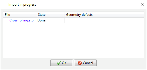
The geometric model of for cross rolling processes includes the workpiece itself and the deforming tool (rolls, rullers, Discher disks, mandrel). The geometry file imported from the CAD system (*.step, *.stp) must contain all the objects necessary for simulation . We recommend to make positioning of all geometric objects in the CAD system. Let's consider several ways of geometry import. 1. Direct Import To loading objects, execute the actions: •Go to tab Geometry; •Click on the button Load from file (3D) and in the window that opens, select the file (*.stp); •When the import process is completed, click the button OK.
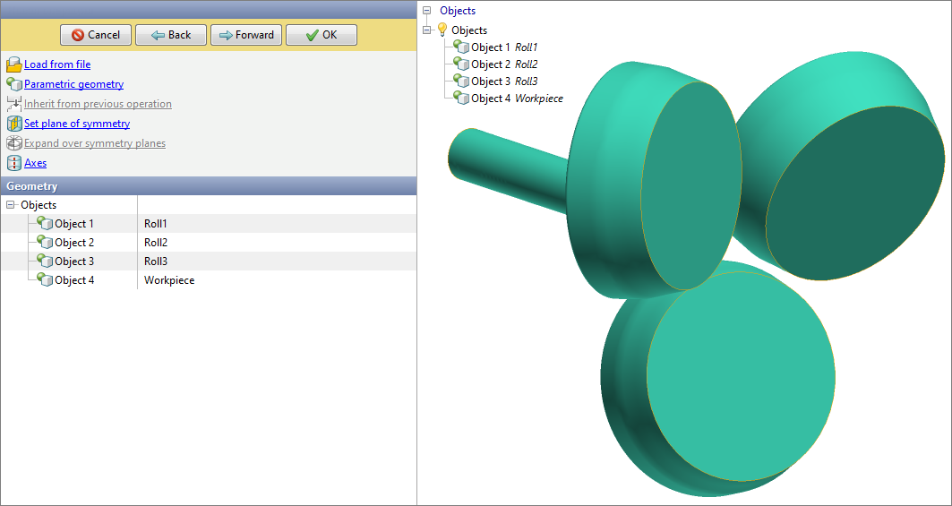
After performing the above actions in the tab Geometryall objects will appear and the 3D model will be displayed in the results window.
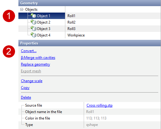
Loaded objects have to be converted according to their type into a workpiece and tools. To do this, select the object (1) and press Convert (2) in object properties.
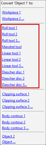
Next, in the window that opens for the workpiece, select the object Workpiece 1. The tools are converted according to its type:
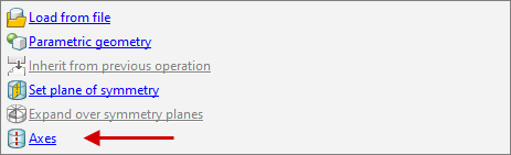
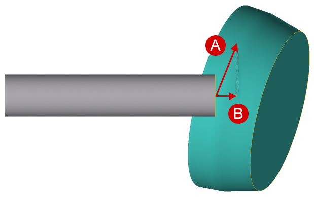
The final and important step in preparing the geometry is to define the axes for the tools which have the rotation movement. It is not necessary to assign axes for tools with a fixed drive. To define axes it is necessary in the tab Geometry go to section Axes.
Further, when clicking on the appropriate tool in the section Properties set the axis. The axis can be calculated automatically after pressing the button Compute or assigned manually. During manual setup it is necessary to know the coordinates of two points lying on the axes or one point and direction in space (vector assignment of the axes).
2. Geometry import from QShape QShape can be used to evaluate the quality of the surface mesh of objects and improve the geometry after the CAD system.QShape can be used to evaluate the quality of the surface mesh of objects and improve the geometry after the CAD system. See also: |
||||
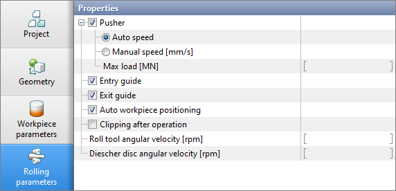
Tab Rolling parameters contains basic info about the drive of tools, the movement of the workpiece by the pusher and the stabilization of the position of the workpiece in space.
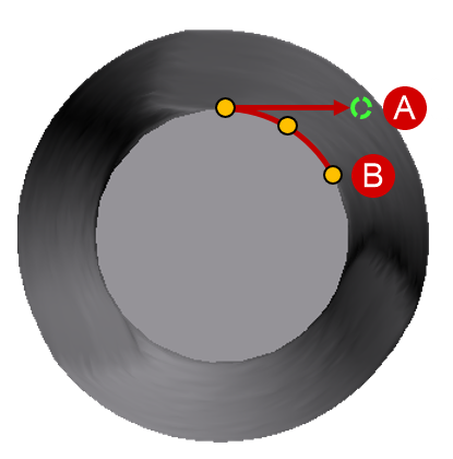
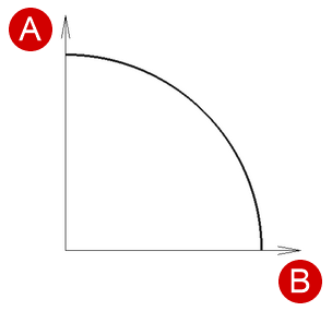
With enabled feature Pusher to workpiece will be transmitted the translation movement. The parameters for translation movement are pusher velocity and maximum load. The pushing velocity can be selected auto or setup manually. •If velocity is specified, the workpiece moves with the constant velocity until the velocity of the workpiece from the contact with the rolls exceeds the set one. •If the max load is specified, then as long as this value is not exceeded, the workpiece is pushed into the rolls even if there is no grip. If the axial resistance exceeds the value of the max load, then the workpiece begins to slip and the process will not be completed. •If both the velocity and the max load are specified, then there is a correspondence between these two parameters, which is schematically shown in the figure.
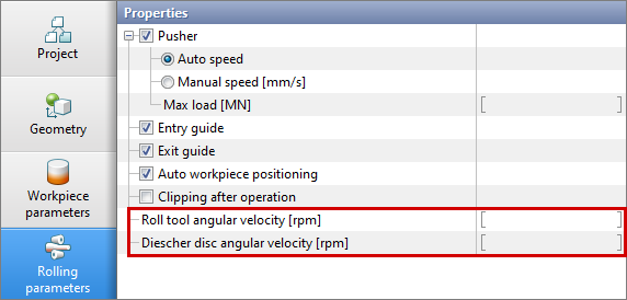
With an increase of the resistance load, the velocity of the workpieces will decrease. Recommended in the tab Rolling parameters set both velocity and max load when using the function Pusher. The recommended value for the max load is 0.1 MN. The tool drive is given by the angular velocity. In the tab Rolling parameters it is possible to set the Roll tool angula velocity and Diescher disc angular velocity.
The direction of rotation is determined automatically, taking into account the features of the process, so that the axial component of the speed is directed in the direction of the rolling axis.
In addition to the pusher and tools drives, it is possible to control the position of the workpiece with help of commands Entry guide and Exit guide. These parameters are analogs to the boundary condition Velocity, which allows to hold the workpiece in a plane perpendicular to the axes of the piercing (rolling) as before entering the stand as well as at the exit from it. These boundary conditions are especially relevant when simulation taking into account the inertial characteristics of the workpiece. It is not recommended to turn off the input and output wiring unless it is necessary. The next option in the tab Rolling parameters is Automatic positioning of workpiece. When this parameter is activated at the first simulation step, the workpiece will be come into the contact with the tool (rolls) in the direction of the rolling axes. The final parameter is Cutting at the end of the operation, which allows at the end of the piercing process to cut the length which specified from the front end. |
||||||||
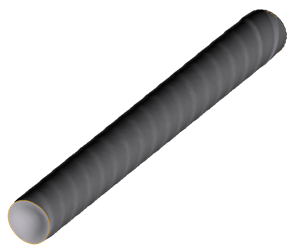
This section will give recommendations on how to set the mesh parameters for processes in the operation type Cross rolling. Setup of mesh parameters is going in the section Simulation parameters tab Mesh in the workpiece. In the operation type Cross rolling no need to change the mesh parameters in the tool (tab Mesh in tool), an explanation will be given below. Important parameters that affect the quality of the results and the velocity of simulation are: multistep shift, adaptation in the contact zone and dual mesh method. Multistep shift allows to divide the simulation step into a specified number of "substeps", which allows you to qualitatively improve the trajectory of the workpiece and increase the convergence of the solution. The recommended default value is 10. Adaptation in the contact zone is a universal parameter for the workpiece and tool. When setting a value > 1 , the mesh will be refined on the tool in domain of the expected contact, as well as on the workpiece inside the deformation zone. Reducing of elements size occurs in proportion to the user defined coefficient. Since the tool is quasi-stationary (the mesh is stationary), this approach allows the mesh to be refined in a relatively small domain, and not over the entire plain surface of the tools, which leads to increase in the simulation accuracy, a decrease in the amount of nodes and, as a result, to a decrease in time costs. By default, this parameter is specified to 10, but to reduce the simulation time without significant loss of accuracy, this parameter can be set in the range [5; 10]. Dual mesh method is enabled by default in the cross rolling module, it allows to keep the surface shape help a geometrical mesh, which can be useful for detecting surface defects, such as a screw line.
The geometrical and computational meshes are interconnected, so on the geometrical mesh, the temperature and strain are recalculated from the computational mesh. That means to ensure the accuracy of the transmission of info about the fields, it is necessary to install a correspondence between the quality of these two meshes. Such correspondence means that the dimensions of the elements of the calculational mesh in the contact area have to be comparable with the dimensions of the elements of the geometrical mesh. |