In the Additional section, you can enable the calculation of auxiliary fields and account for special conditions during the main simulation.
The Workpiece fields block provide additional computed fields that the user can add to the simulation.
Unlike subroutines, the selected fields are computed directly together with the main simulation.
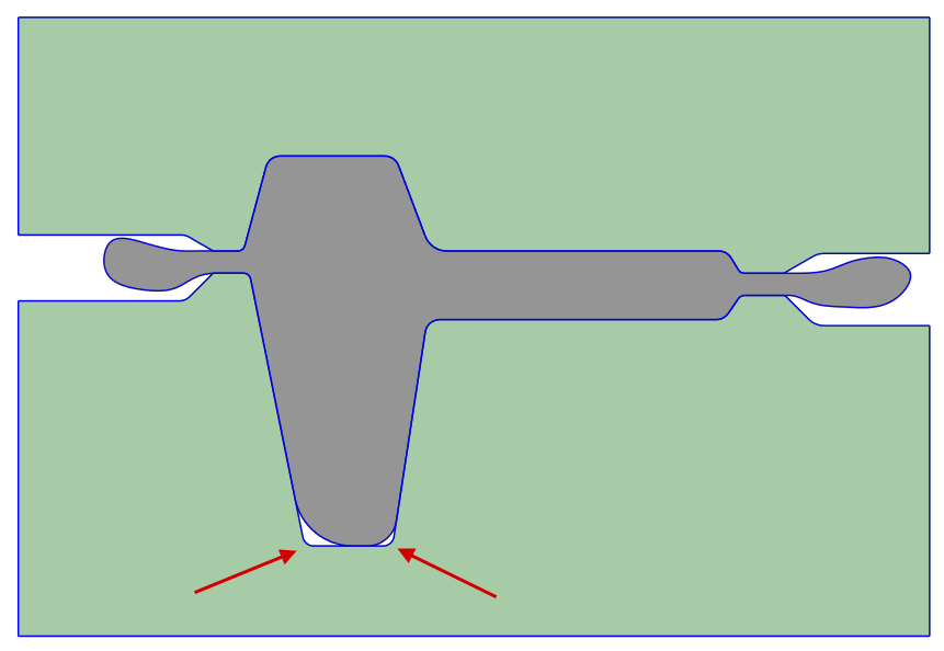
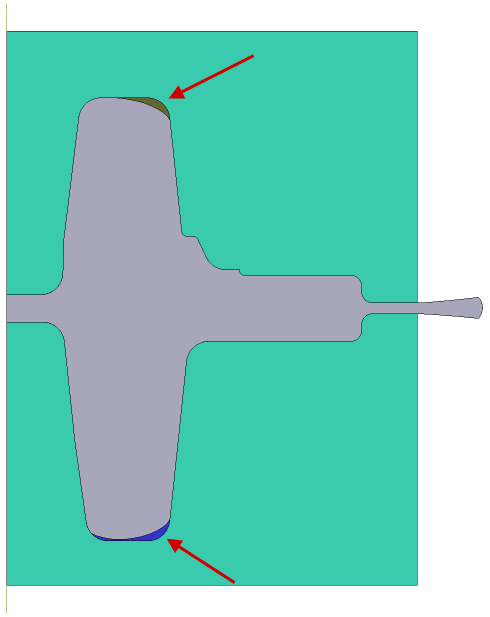
During bulk forging process, when the tool contains deep cavities, the die cavity may remain underfilled due to the pressure of compressed air acting on the deforming material. The program can take into account the change in compressible air pressure according to the adiabatic law p·Vk=const; the initial pressure at the moment of cavity closure is taken as atmospheric, and the adiabatic index k assumed to be 1.4 by default.
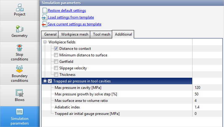
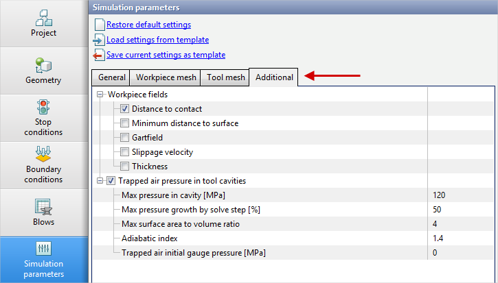
To account for this effect during bulk forging simulation, go to the Simulation parameters tab, open Additional, and enable Trapped air pressure in tool cavities. The following parameters will become available:
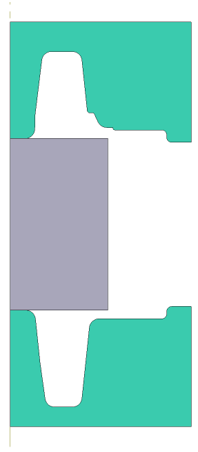
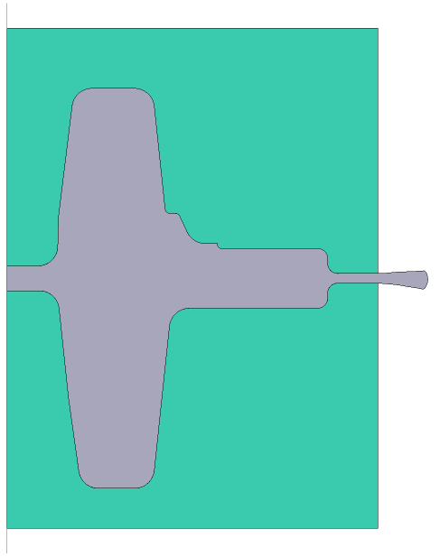
Max pressure in cavity [MPa] is an upper bound on the pressure that can be reached during gas compression. Max pressure growth by solve step [%] - the pressure increase per step cannot exceed the specified value. Max surface area to volume ratio - used to assess the "flatness" of cavities. Two spheres are computed for each cavity. The first sphere is equivalent to the cavity by surface area, and the second sphere is equivalent to the cavity by volume. If the ratio of the diameters of these spheres is greater than the specified parameter value, the cavity is no longer considered. Use pressure multiplier - the pressure increment per simulation step is additionally multiplied by this value. Can be used for exploratory purposes. Consider a hot bulk forging process on a hydraulic press without considering the pressure in the closed cavities of the die:
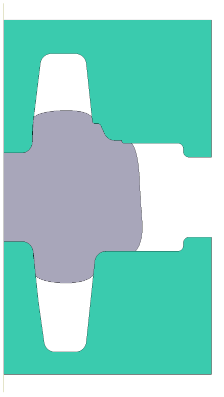
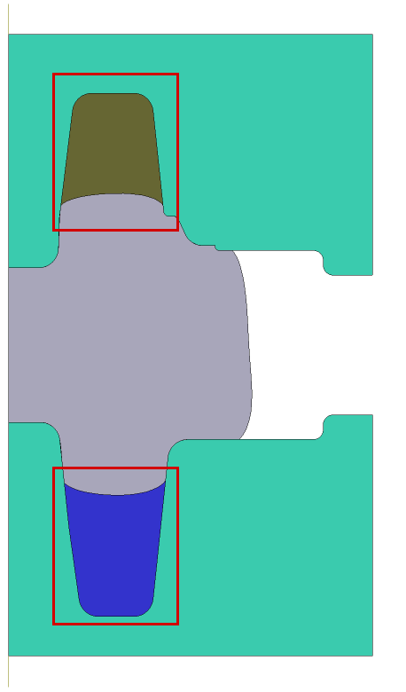
Below, the simulation of the same process is presented, but with considering the pressure of compressible gases. At the moment of closure of the die cavities, the calculation of the volume [mm3] and pressure [MPa] of the gas in these cavities begins:
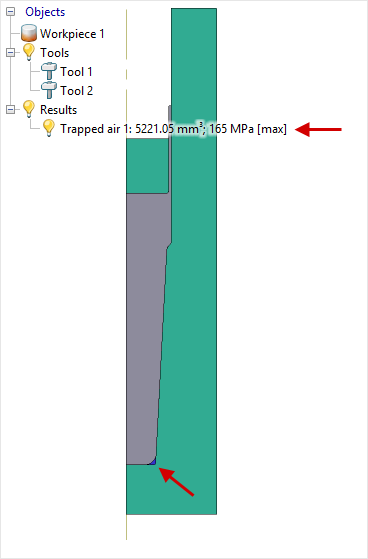
In 2D simulations, information about trapped cavities is displayed in the object tree:
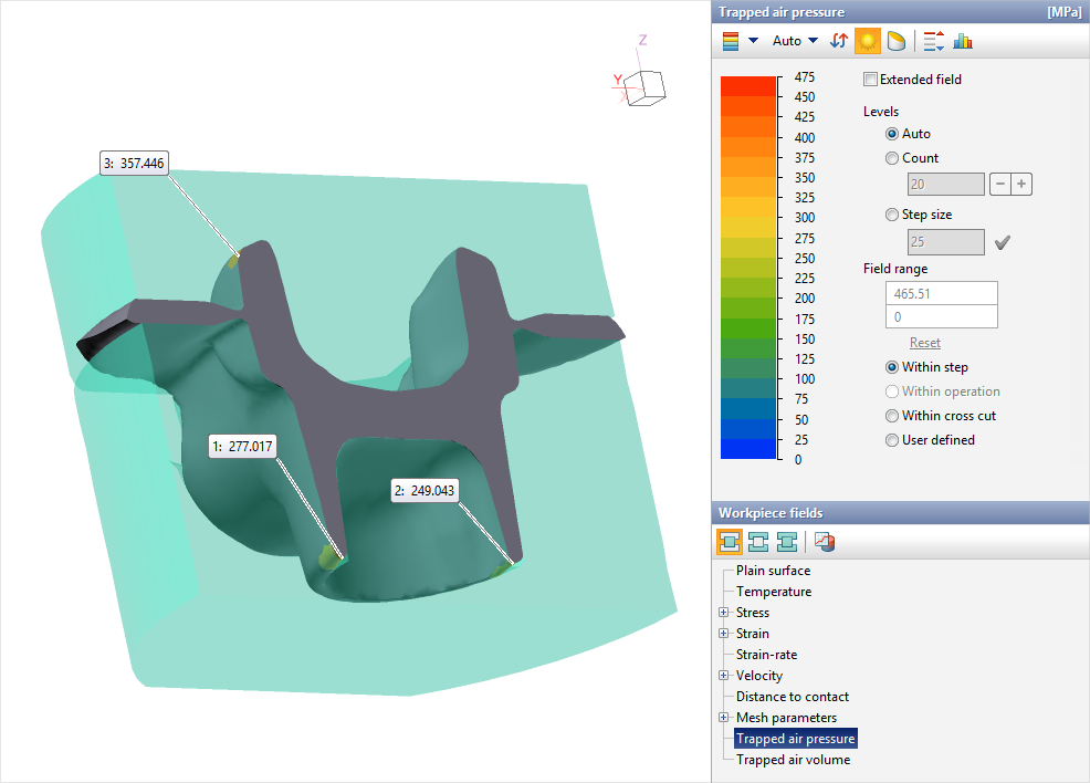
In 3D simulations, this information is not shown in the object tree; however, surface computed fields are available for the workpiece: Trapped air pressure and Trapped air volume:
In production, gas is vented from the closed cavities either into the gap between the ejector and the die or by means of special gas venting channels. |