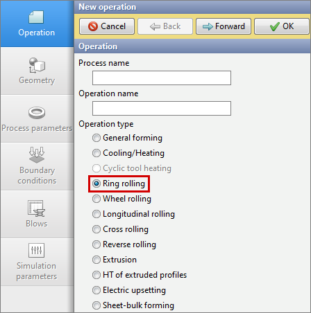
Ring rolling operation type is designed to simulate the ring rolling processes of various types of rings. To activate the module, you must select Operation type – Ring rolling. The module takes into account the specifics of the process and simplifies the setting of boundary conditions for users.
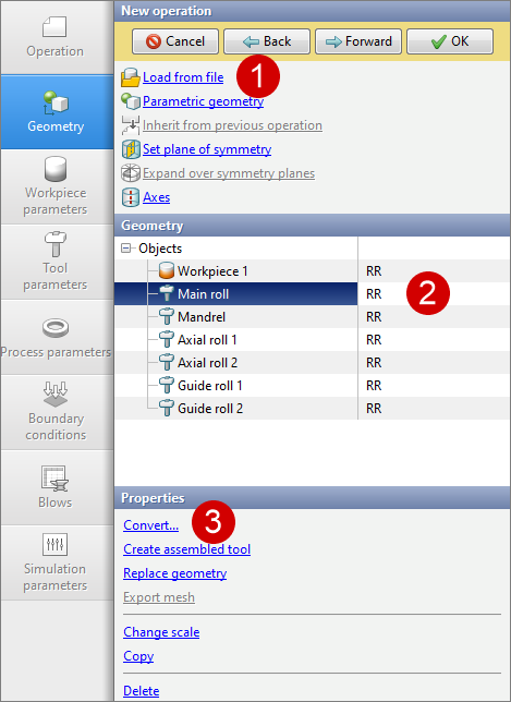
In the Geometry tab it is necessary to load the initial geometry of objects for simulation. Each object must be converted to the corresponding rolling mill tool: Main roll, Mandrel, Axial roll, Guide roll. Objects types can be assigned in the QShape geometry editor. If they are not pre-assigned, they can be converted after the loading the geometry into QForm UK in the Geometry tab with the help of Convert... command
The material and initial temperature of the annular workpiece are assigned in the Workpiece parameters tab. If there are preliminary operations, the workpiece temperature can be inherited.
It is necessary to specify the lubricant, material and tool temperature in the Tool parameters tab. When rolling rings, it is recommended to use a lubricant with a Siebel friction model with a friction factor of 0.9 and a heat transfer coefficient of 5000-10000 W/m2K for tools.
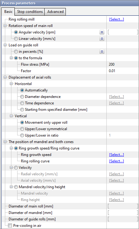
It is necessary to set the initial data and mill properties in the Rolling parameters tab.
There are three sections in the rolling parameters tab: Basic, Stop conditions, Advanced. Let's consider each of them separately.
•Ring rolling mill - in this section it is should be set the mill parameters to obtain the most accurate simulation results. For more information, see the Ring rolling mill section. •Rotation speed of main roll - parameter that characterizes the kinematics of the main roll. Can be set as a constant or variable value (depending on the current diameter of the ring). It is possible to specify it as Angular velocity or Linear velocity. •Load on guide roll - parameter that characterizes the load of the guide rolls on the workpiece. If in percents option is activated, then the load will be a user defined percentage of the maximum summary load, specified in the parameters of the ring rolling mill. If to the formula option is activated, then it is should be specified the flow stress (a certain average value for a specific technological process) and a coefficient (factor), calculations are made using the formula below: where factor - some multiplier, recommended value 0.01. s - ring thickness [mm] ([inch]); h - ring height [mm] ([inch]); d - outer diameter of the ring [mm] ([inch]). •Displacement of axial rolls - parameter that characterize the kinematics of axial rolls. The translational motion of axial rolls can be in two directions, so it is possible to specify a motion law for each direction: 1. Horizontal - displacement of the axial rolls in the horizontal direction (along the axis X). If automatic displacement is activated, the rolls will move at a velocity equal to half the velocity of the ring growth speed. You can set a table roll displacement as a function of ring outer diameter or time, or you can displace rolls starting from specified diameter. 2. Vertical - displacement of the axial rolls in the vertical direction (along the axis Z). You can move either only the top roll, or both rolls symmetrically at the same velocity, or both rolls with a certain speed ratio.
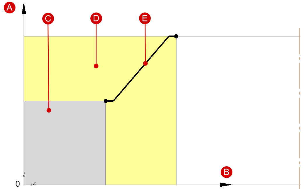
Setting the kinematics of tools in the radial and axial directions: •The position of mandrel and both cones - parameter that determines the conditions of ring deformation through the laws of motion of the mandrel and axial rolls. 1 . Ring growth speed/Ring rolling curve - parameters that must be set in tabular form. Ring growth speed depends on the diameter, and the ring rolling curve is the dependence of the ring thickness on the ring height. Examples of ring growth speed curves and ring rolling curves are shown below:
2. Velocity - tool motion parameters specified tabularly as a function of time. Respectively radial velocity - the mandrel speed in the radial direction, and axial velocity - the speed of axial rolls in the axial direction (along the Z axis). 3. Mandrel velocity/ring height - tool motion parameters specified tabularly as a function of outer diameter. Mandrel velocity determines the law of motion of the mandrel in the radial direction, and ring height determines the law of motion of axial rolls in the axial direction. •Diameter of main roll and Diameter of mandrel - parameters primarily required for calculating the ring wall thickness.
•Parameter pre-cooling in air allows you to take into account the cooling of the ring before rolling. In this case, convective heat exchange with the environment occurs. |
||||||||
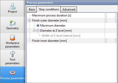
Time stop: •Maximum process duration - time after which the process must be guaranteed stopped. Stopping by outer diameter: •Finish outer diameter - parameter that determines the stop condition when a specified outer diameter is reached. 1. Maximum diameter - is a parameter that allows to stop if the value of the outer diameter in any of the sections equals or exceeds the user defined value. 2. Diameter at Z-level - it is possible to specify the value of the coordinate Z in which the diameter should be measured. 2.1 Width of Z-level interval - the interval within which the maximum diameter must be found. Stopping by inner diameter: •Finish inner diameter - parameter that determines the stop condition when the user defined inner diameter is reached.
|
||||
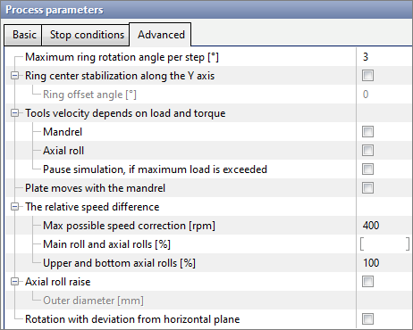
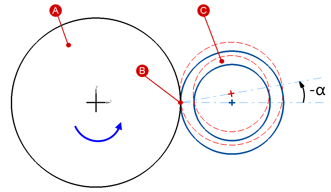
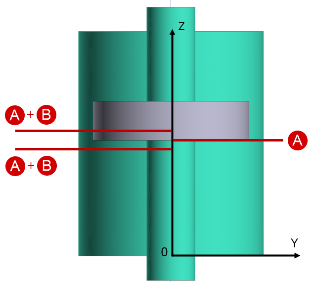
•Maximum ring rotation angle per step - parameter affecting the algorithm for calculating the simulation step, as well as the stability of the deformation zone. Recommended values are 3-6 degrees. •Ring center stabilization along the Y axis - parameter required to restrict the displacement of the ring center in the Y-axis direction. Can be activated in the absence of guide rolls. If necessary, you can set the ring offset angle. In case of positive values of the angle, the ring will offset towards the entrance, in case of negative values – towards the exit. A scheme of the ring offset is shown below:
Tools speed correction: •Tools velocity depends on load and torque - a set of parameters that are connected with the parameters specified in the ring rolling mill.
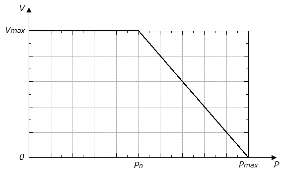
1. Mandrel - it is possible to control the mandrel velocity depending on the current load value. In this case, it is necessary to specify the following parameters for mandrel in the ring rolling mill: nominal load (Pn), maximum load (Pmax) and maximum velocity at nominal load (Vmax). A graphical dependence of velocity on load is shown in the figure below. When the nominal load is obtained, the velocity will begin to decrease linearly.
2. Axial roll - it is possible to control the axial roll velocity depending on the current load and torque values. In this case, it is necessary to specify the following parameters for axial rolls in the ring rolling mill: nominal load, maximum load, maximum velocity at nominal load, nominal torque, maximum torque. As for the mandrel, when the nominal values of load and torque are reached, the velocity will begin to decrease linearly. 3. Pause simulation, if maximum load is exceeded - when this parameter is activated, the simulation will be stopped after reaching the maximum load according to the value in the ring rolling mill.
•Plate moves with the mandrel - the possibility to move the table at the same speed as the mandrel. Relevant when using a table in the form of a geometric body.
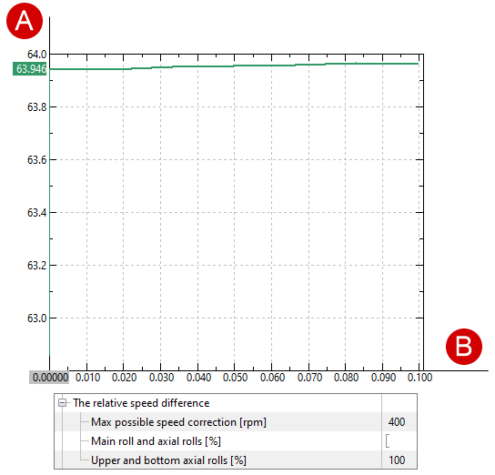
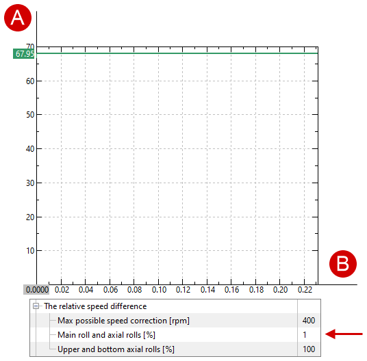
•The relative speed difference - parameter used to decrease/increase the rotation speed of the axial rolls. 1. Max possible speed correction - the value relative to which the rotation speed of the axial rolls changes. 2. Main roll and axial rolls - percent ( k) from the max possible speed correction, by which the speeds of both axial rolls can be changed.
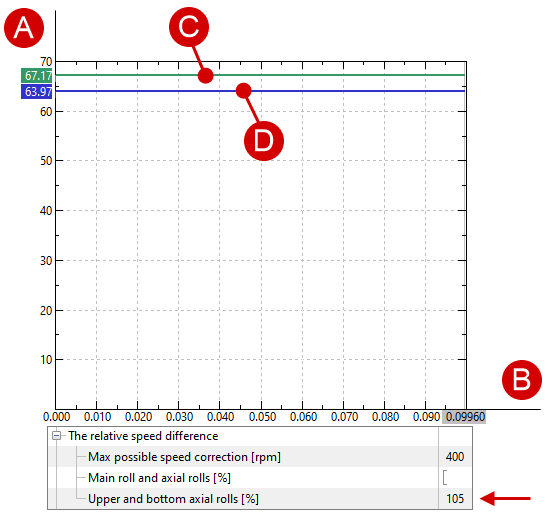
where nax_new - new rotational speed of axial rolls after correction; nax - current rotational speed of axial rolls; MC - maximum possible speed correction; k - percentage of rotation speed change, can be either a positive or negative value. 3. Upper and bottom axial rolls - percent ( k), showing the relative difference in the rotation speeds of the upper and lower axial rolls. The default value of 100% means that both axial rolls rotate at the same speed. Increasing (decreasing) the value of this parameter will lead to an increase (decrease) in the rotation speed of the lower axial roll in relation to the speed of the upper one.
Where n ax_2 - new rotation speed of the lower axial roll after correction; n ax_1 - current rotation speed of the upper axial roll; k - percentage of rotation speed change. 1) Default parameters:
The rotation speed of both axial rolls is the same. 2) The relative difference in rotation speeds of the main roll and axial rolls is 1%:
The rotation speed of both axial rolls is the same and 4 rpm faster than in the first case. 3) The relative difference in rotation speeds of the upper and lower axial rolls is 105%:
The rotation speed of the lower axial roll is 5% higher than the rotation speed of the upper roll.
•Axial roll raise - parameter used to raise the axial roll. 1. Outer diameter - the value of the ring diameter after which the axial roll will be raised.
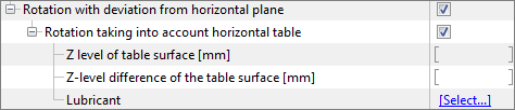
Virtual table: •Rotation with deviation from horizontal plane - after activating, allows the ring to be distorted in the horizontal plane. •Rotation taking into account horizontal table - after activating, allows to use a virtual table in the simulation. Additional parameters will appear.
1. Z-level of table surface - Z-axis coordinate where the virtual table should be located. 2. Z-level difference of the table surface - table level difference for the entrance part of the ring (from the -OY direction). Positive values will raise the table level relative to the specified level, negative values lower it.
3. Lubricant - is necessary to take into account the coefficient of friction, as well as for correct heat transfer in contact with the table. |
||||||||||||||
The Simulation step multiplier located in the Simulation parameters tab is a distinctive feature of the ring rolling operation type.
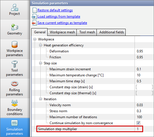
Simulation step multiplier - parameter that proportionally changes the time of the simulation step. The algorithm calculates the simulation step and if the multiplier is not equal to 1, the calculated step value is multiplied by the multiplier, the result is a new step of shifting the system.