In this section, a simulation example of quenching and tempering of a X12Cr13 steel shaft is considered.
Initial data
Operation 1 - Quenching |
||
Operation |
Operation type |
Cooling/Heating |
Problem type |
2D axisymmetric |
|
With elastic-plastic deformation |
Activated |
|
Geometry |
Load from file |
C:\QForm UK\12.0.1\\geometry\heat_treatment\shaft_heat_treatment |
Workpiece parameters |
Material |
Standard/Phase transformations/X12Cr13 mixture |
Initial phase |
Austenite |
|
Temperature [˚C] |
1000 |
|
Stop conditions |
Field value |
Temperature |
Bound value [˚C] |
80 |
|
Bound type |
Less or equal |
|
Region in object |
Fraction of volume |
|
Fraction of volume [%] |
100 |
|
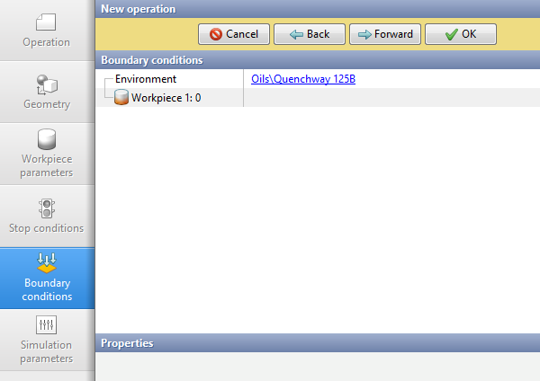
Boundary conditions |
Environment |
Oils/Quenchway125B |
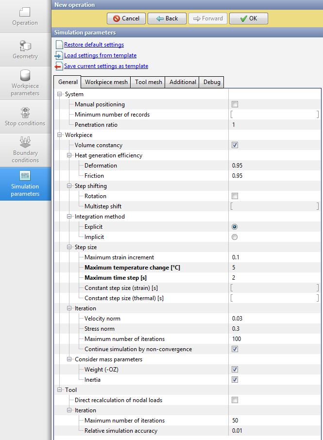
Simulation parameters |
Maximum step size [s] |
4 |
Maximum temperature change [˚C] |
10 |
|
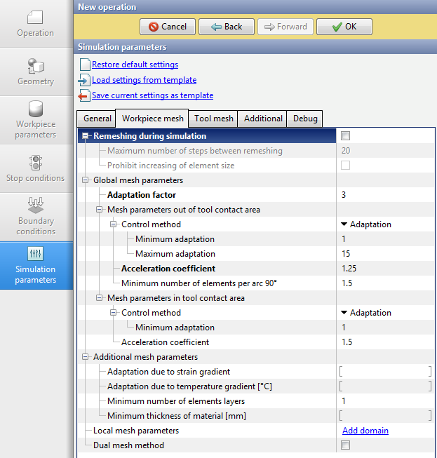
Remeshing during simulation |
Disabled |
|
Adaptation factor |
4 |
|
Acceleration coefficient |
1.25 |
|
Operation 2 - Tempering |
||
Operation |
Operation type |
Cooling/Heating |
Problem type |
2D axisymmetric |
|
With elastic-plastic deformation |
Activated |
|
Geometry |
Workpiece |
Inherited from previous operation |
Workpiece parameters |
Material |
Inherited from previous operation |
Initial phase |
Inherited from previous operation |
|
Temperature |
Inherited from previous operation |
|
Stop conditions |
Time [s] |
7000 |
Boundary conditions |
Environment |
Created manually |
Environment temperature |
Up to 6000 s - 600 ˚C (furnace), after 6000 s - 20 ˚C |
|
Heat transfer coefficient |
Up to 6000 s - 2000 W/m2K (furnace), after 6000 s - 30 W/m2K |
|
Simulation parameters |
Maximum step size [s] |
20 |
Maximum temperature change [˚C] |
15 |
|
Remeshing during simulation |
Disabled (the workpiece mesh will be inherited from 1 operation) |
|
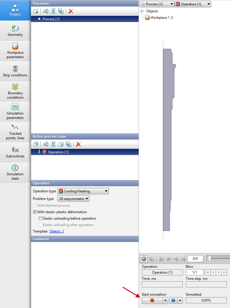
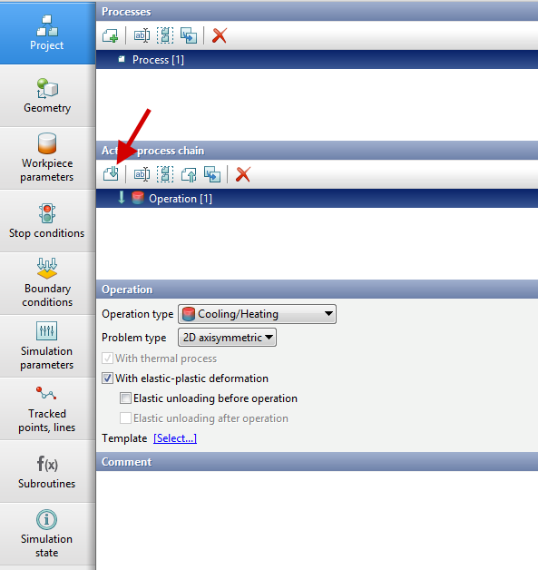
1.Click Create new process.
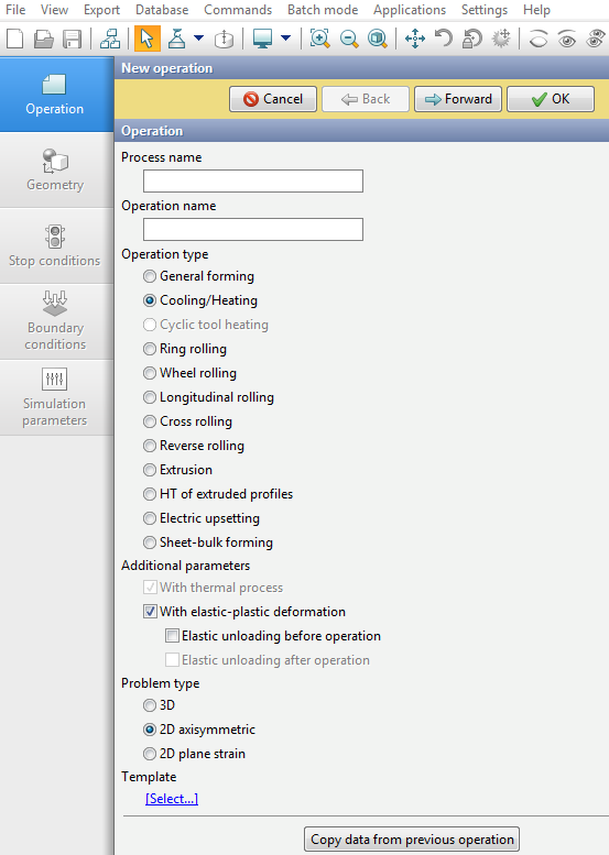
2.In the Operation tab, select Process type - Cooling/Heating, Additional parameters - with elastic-plastic deformation, Problem type - 2D axisymmetric. Click Forward. If you click OK, you can then switch between tabs manually in any order..
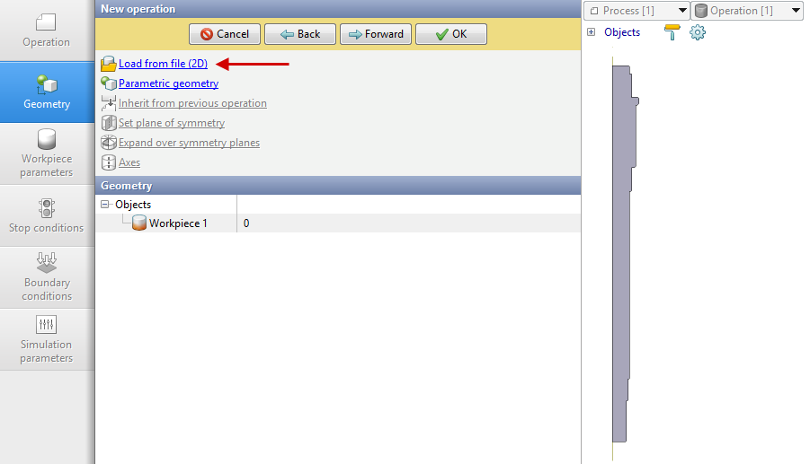
3.In the tab Geometryclick Load from file (2D).. Select file shaft_heat_treatment(default:C:\QForm UK\12.0.1\\geometry\heat_treatment\).. Convert the object into a workpiece. Click Forward.
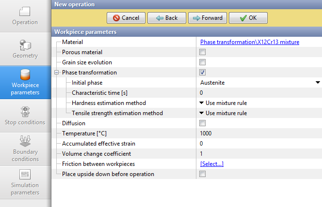
4.In the Workpiece parameters tab, select the material Phase transformation\X12Cr13 mixture. Activate option Phase transformations. Set the temperature 1000 °C. Click Forward.
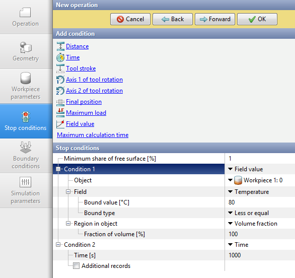
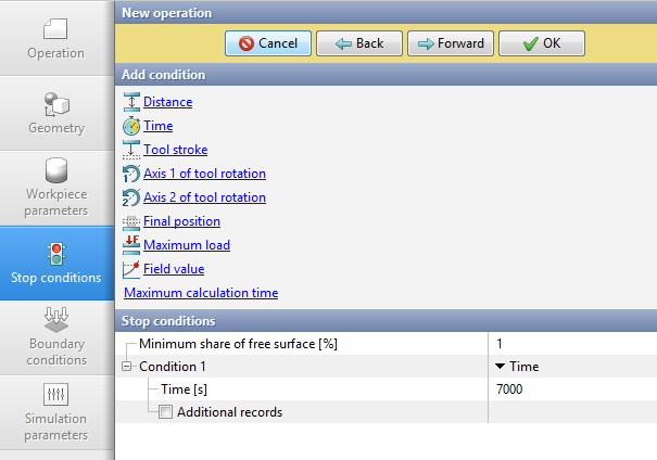
5.In the Stop conditions tab, set a condition to stop the process when the workpiece temperature does not exceed 80˚C. To do this, in the Add condition menu, click on Field Value. For Field, select Temperature. Set 80 for Bound value [˚C]. Switch Bound type to Less or equal. Set Region in object to Volume fraction [%]. Set the value 100.
The program also requires an additional stop condition Time. To do this, under Add Condition, click on Time. Set the value 1000s. Press Forward..
6.In the Boundary conditions tab, select Environment -Oils\Quenchway 125B . Click Forward.
7.In the Simulation parameters tab, under General set Maximum temperature change [˚C] - 10, set Maximum step size [s] - 4 s.
Go to the Workpiece mesh tab. Set Adaptation factor to 4, set Acceleration coefficient to 1.25. Disable Remeshing during simulation. Click OK..
8.Run the calculation. To do this, click on the red calculation start button . The program will offer to save the project. It is necessary to agree and select the project storage directory.
9.Go to the Project tab and click Add operation to process chain.
10.Fill in the fields in the Operation tab in the same way as for operation 1 in step 2. Click Forward.
11.Leave the parameters in the Geometry and Workpiece parameters tabs unchanged. The values of these parameters are inherited from operation 1. Click Forward.
12.In the Stop Conditions tab, set the Time condition. Set the value to 7000s. Click Forward.
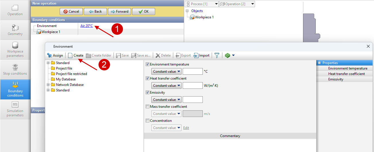
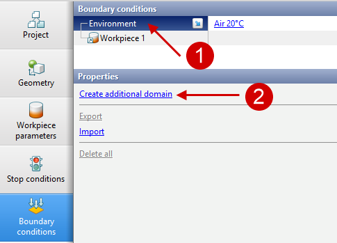
13.In the Boundary conditions tab, create the boundary conditions manually according to the initial data. First, click on the initial environment (1) to open a window with the Environments database. In the window that appears, click Create (2).
Create a boundary condition with furnace parameters for a 6000 s process.
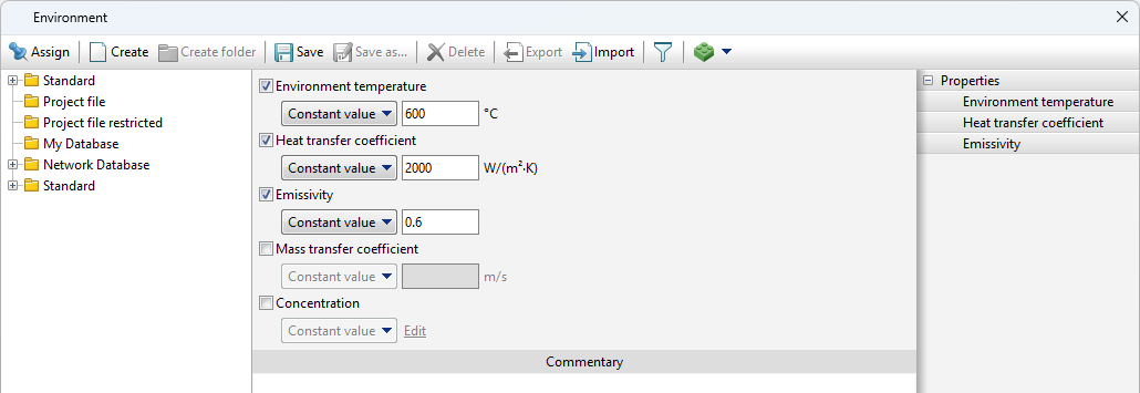
Save to the Project file under the name '600 C'.
14.In the Boundary Conditions tab, click on Environment (1), then click on Create additional domain (2).
Next, select the rectangular shape of the area and set its dimensions so that it completely overlaps the workpiece. Set the previously created environment '600 C'. Set Turn-off Time [s] 6000.
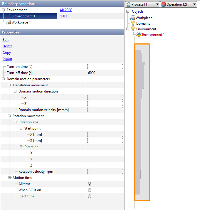
Click Forward.
15.In the Simulation parameters tab, set Maximum temperature change 15 °C, Maximum step size [s] 20 s. Go to Workpiece mesh. Disable Remeshing during simulation - this way the mesh is inherited from the first operation and will not change. Click OK.
16.Run the calculation of the second operation.
17.After the calculation, the results should be analyzed. When calculating with the 'Phase Transformations' option enabled, additional workpiece fields are available.
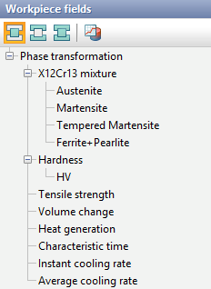
Description of these fields:
•X12Cr13 – phase composition. This field is named after the name of the workpiece material used. The phase fields (in this example Austenite, Martensite, Temprered Martensite, Ferrite+Pearlite) show the percentage of each phase;
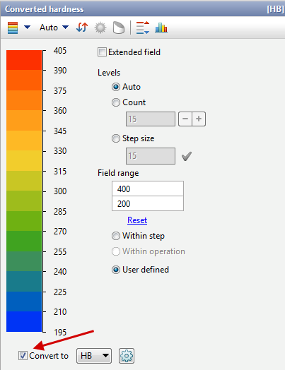
•Hardness - hardness calculated in one of 2 ways. It is also possible to output hardness converted to another type:
•Tensile strength [MPa] - the tensile strength calculated in one of 2 ways;
•Volume change [%] - volume change during phase transformation;
•Heat generation [kJ/kg] - release (or absorption) of latent heat during phase transformation;
•Characteristic time [s] - the time that the workpiece is in the characteristic temperature range (specified in the material parameters in the Characteristic temperature interval);
•Instant cooling rate [°C/s] - cooling rate at the active step;
•Average cooling rate [°C/s] - cooling rate averaged from the beginning of the process.