The subroutine calculates a set of fields to estimate how much the surface of the workpiece is stretched during deformation and whether the undersurface material layer is pulled inside the workpiece.
Output fields
Field name |
Dimension |
Comment |
|---|---|---|
expansion_ratio |
Dimensionless (area ratio) |
Surface field, shows how many times the surface area has changed relative to the original surface area. The value can be either greater than 1 (increase in area) or less than one (decrease in area) |
gartfield |
Dimensionless (strain) |
Surface field that accumulates on those areas of the workpiece surface where undersurface layer thickening occurs. The value of the field may decrease as the thickness of the undersurface layer decreases |
gartfield_inward |
Dimensionless (strain) |
Surface field, which accumulates in those areas where the undersurface layer thickening and, at the same time, the material flows only into the workpieces. The value of the field may decrease as the thickness of the undersurface layer decreases |
Estimation of surface flow defects help the Gartfield fields
QForm UK allows you to simulate metal forming with high accuracy. Thanks to this, costs are significantly reduced when introducing forging technologies for forgings of the highest complexity into production. At the same time, the finite element method used does not explicitly predict a number of defects present in real forgings, so there is a need to use additional criteria for evaluating the calculation results.
The following methods are implemented to evaluate metal flow defects in QForm UK:
1.Tracing undersurface flow lines.
2.Field Minimum distance to surface.
3.Standard post-processing subroutine Surface flow analysis.
Standard subroutine Surface flow analysis is calculated after simulation of the main deformation process. You can add it for calculation on the panel Initial data, in the tab Subroutines:
|
Information |
If a chain of consecutive operations is simulated, the field will start accumulating from the operation where the subroutine was added. For this reason, the value of the accumulated field at the last operation of the chain depends on in which operation the subroutine is added |
|
The gartfield is calculated based on tensile strains in the direction normal to the surface of the workpiece being deformed and is a surface field. It is assumed that at the place of accumulation of such tensile strains, defects of the “flow-through defect” or “suck-in defect” type occur.
Scale values are limited by default from 0.3 to 1. On the basis of summarized experimental data at Gartfield values from 0.7 and above, there is a probability of defect appearance in this part of the forging surface.
|
Information |
Limiting the scale for the gartfield and gartfield_inward fields between 0.3 and 1 is just a recommendation. Based on your experience comparing the calculation results with experimental data, these values can be modified when making decisions about the criticality of the defect for the technology used |
|
The gartfield_inward field is only accumulated at places where, in addition to thickening of the undersurface layer, there is material movement inside the workpiece. This additional filter helps to identify exactly where material is being pulled from the surface into the workpiece.
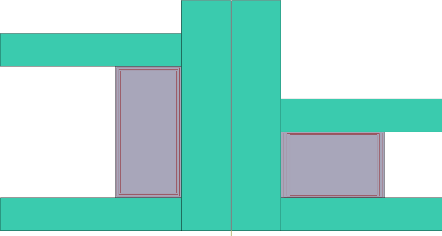
As an example, we can consider ring upsetting, in which a clear thickening of the undersurface layer along the outer and inner surfaces is visible.
|
Simulation results of the ring upsetting. Left - initial state, right - final state |
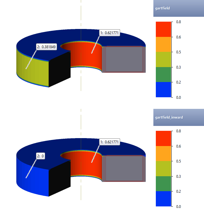
It is clearly visible that the gartfield_inward field accumulates only along the inner surface of the ring, since it is there that the material movement inside the deformed workpiece takes place.
|
Difference between gartfield and gartfield_inward fields during ring upsetting |
|
Information |
For convenient analysis of surface fields in 2D computations, it is recommended to enable 3D display mode, as in the figure above |
|
Compared to other methods for determining surface flow defects, the field gartfield has the following advantages:
1.Fast simulation speed (compared to undersurface flow lines tracing).
2.The field is displayed immediately on the entire surface of the workpieces (the minimum distance to the plain surface field and traced undersurface flow lines must be viewed in a user defined cross cut plane).
3.Sensitivity to element size is lower than the field Minimum distance to surface.
4.There is no problem inherent in undersurface lines, namely degradation of the line array into a single line, after which the undersurface lines become unusable for analysis.
|
|
|
|
|
Simulation results, the field gartfield and the experiment |
||||


