The subroutine calculates a set of fields that allows to evaluate the degree of refinement of the original structure of the workpiece material using a widely used parameter such as “Forging ratio”.
Subroutine parameters
Parameter name |
Dimension |
Comment |
|---|---|---|
Initial forging ratio |
Dimensionless (strain) |
The value of the initial Forging ratio, accumulated to the operation in which the subroutine is added |
track_x, track_y, track_z |
Dimensionless |
Components of the unit vector that specify the direction of the axes of the initial workpieces. This is either the rolling direction or the axis of the ingot |
Output fields
Field name |
Dimension |
Comment |
|---|---|---|
track |
Dimensionless |
Vector field representing the current direction |
track_x, track_y, track_z |
Dimensionless |
Components of vector field track |
forging_ratio |
Dimensionless (strain) |
Volumetric field displaying the Forging ratio distribution in the workpiece |
The widespread use of the Forging ratio concept in manufacturing is due to the availability of measurement of this parameter. Usually, Forging ratio is calculated as the ratio of the lengths of the workpiece before and after deformation or as the ratio of the cross-sectional areas before and after deformation. In a sequence of operations, the Forging ratio values after the individual operations are multiplied to obtain the final Forging ratio.
|
Forging ratio calculation for a sequence of forging operation. A - Billeting, B - Upsetting, C - Cogging |
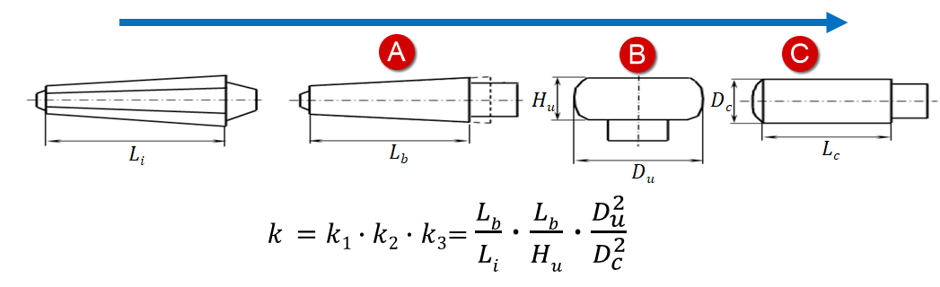
It is easy to see that in order to calculate the Forging ratio, it is necessary to determine the direction along or across which the measurements are taken. This is also the reason why this parameter is limited, because if the deformation of the workpiece does not change the length of the workpiece along the selected axis, it will be considered that there is no deformation.
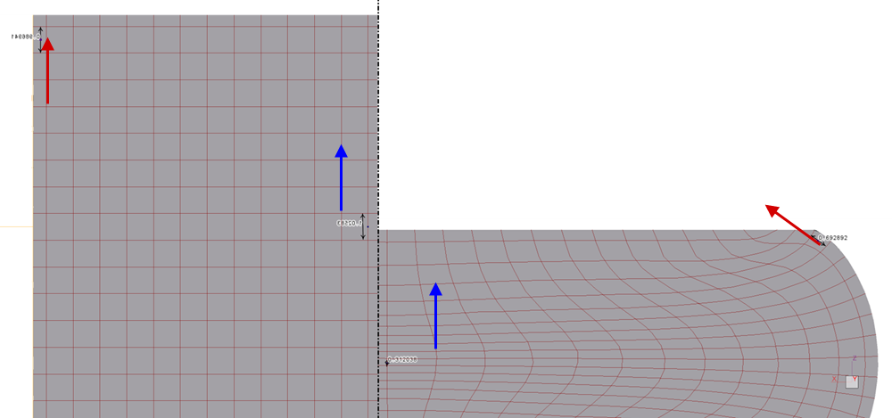
In QForm UK it is necessary to set the direction of the workpiece axis before starting the subroutine calculation. Usually this is either the rolling direction or the axis of the ingot. Further, Forging ratio will be calculated taking into account this direction, and this direction does not remain global. The initial direction is set in each finite element and rotates with the element as it is moved or deformed. This feature leads to some difference between the value of the parameter calculated in QForm UK and the value calculated by the formula, but it allows to calculate the Forging ratio even in processes with complex flow of the workpiece material.
|
Direction for Forging ratio calculation before upsetting the cylinder with flat tools (left) and after upsetting (right) |
In addition, Forging ratio constantly accumulates during deformation along a user defined direction. Thanks to this, at any step of the calculation, you can see the current Forging ratio value without having to multiply anything else.