The subroutine allows you to obtain fields of coordinates of workpiece points and their displacement in axial directions.
Output fields
Field name |
Dimension |
Description |
|---|---|---|
coord_1, coord_2, coord_3 |
mm |
Coordinates of points at the initial moment of time in the directions of the x, y, z axes relative to the zero coordinate |
disp |
mm |
Vector field displaying the displacement of workpiece points relative to their initial position |
disp_x, disp_y, disp_z |
mm |
Displacement of workpiece points relative to their initial position in the x, y, z axes directions |
displacement |
mm |
Displacement of workpiece points relative to their initial position |
Using the subroutine to track the position of an end face of the workpiece
This subroutine can be used as a tool for tracking the location of the workpiece end faces in forging. To do this you need:
1. Add the Displacement subroutine and simulate it for the process.
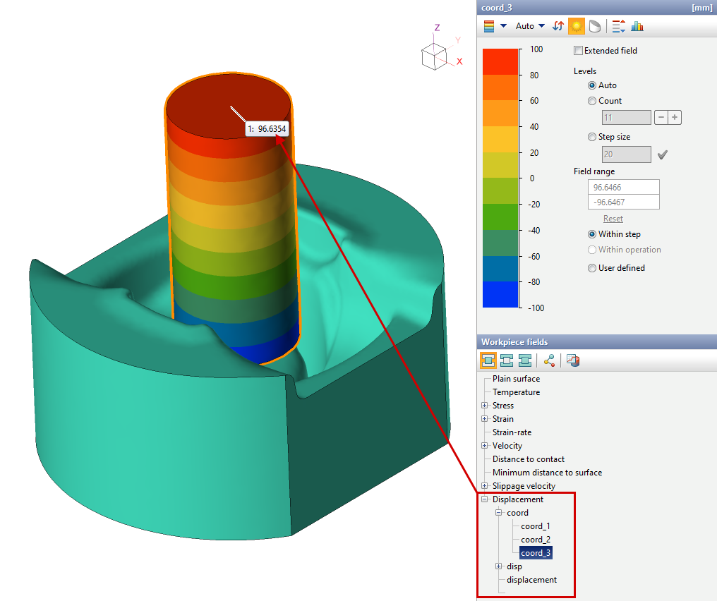
2. Determine the axial coordinate of the end face. In this example, this is the field value coord_3, since the height of the workpieces changes along the z axes . Use the coord_1 and coord_2 fields for the x and y axes .
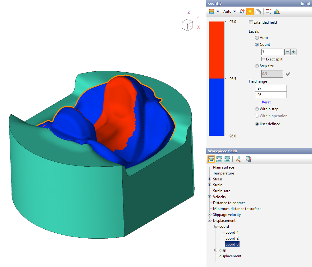
3. Set up the scale as in the figure below: to do this, you should set the amount of divisions to 3, install the field range so that the coordinate of the end face is approximately equal to the value in the middle of the scale (which separates different color, in this example - red and blue).
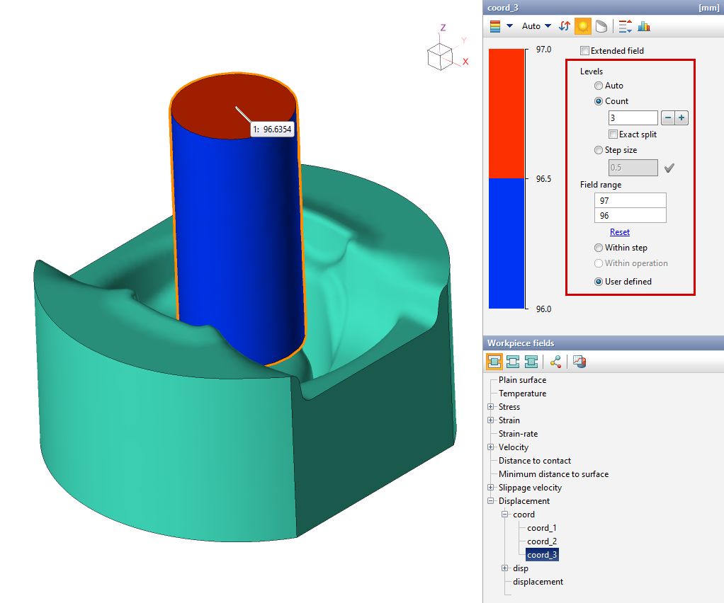
4. Now you can change the simulation step to track how the position of the material from the end face changes.