QShape converts geometric fit by created in CAD-systems, into finite element fit by. The figure below schematically shows the converting sequence:
Initial geometry imported from solid STEP or IGES:
1 |
Importing a rigid body from a STEP, IGES or x_t file |
2 |
Shell (Shell) |
3 |
Solid (solid body) |
4 |
Named fit by (WPiece, TOOL1, TOOL2, etc.) |
Below is a comment of the structure of models at each stage of preparing geometry in the editor QShape:
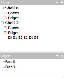
Shell (shell) After selecting a Geometric Set object and executing the Make Shell command, or when importing source geometry from a solid STEP or IGES file, the Shell appears in the Model window. If there are several shells, then they are numbered as Shell 0, Shell 1, Shell 2 etc.:
Shell consists of surfaces (faces) and edges (Edges). Their collections are revealed in the window Fit by after clicking the [+]. When a plain surface or edge is selection , in turn, another list is opened in the window Object: if the plain surface is selected, then in the window Object the edges related to this plain surface will be shown, if an edge is selected, then the plain surface related to the selected edge will be shown (as in the figure above). Object Shell has a structure inherited from CAD-fit by. This means that its plain surface are represented in parametric form in the view of splines or analytical surfaces in the same way as they were written in the original geometry file .
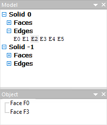
Solid (solid body) Selecting an object Shell, it needs to be split into finite elements help the commands Mesh generation. After this converting Shell changes name to Solid. Object still retains its structure with the same number of surfaces and edges, but now its plain surface are split into triangular finite elements. Solid is a finite element representation of a geometric object with the original structure saving :
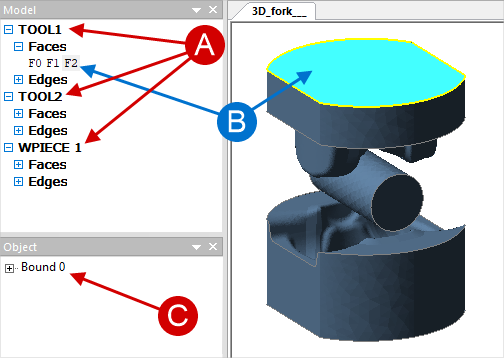
Named model To obtain the final structure of an object, it must be convert to a named fit by help the commands Convert. This may be a workpiece (WPIECE) or some tool (TOOL1, TOOL2, …). There is a further converting of the structure of the fit by: plain surface are enlarged, and the amount of edges is reduced. Only those edges remain where the plain surface undergoes a break. Edges that form closed contours are called boundaries (bounds), they separate new enlarged plain surface from each other. Non-closed sequences of edges form chain (chains) and are sharp edges within one enlarged plain surface. These chain (chains) can adversely affect the stroke of simulation, and in some cases they need to be corrected:
The named fit by is intended for carrying out computations. If necessary, the named objects can be moved, rotated, display symmetrically, rotated with respect to symmetry planes (that is, doubled, quadrupled, etc.). |
The Objects that make up the fit by are plain surface (faces) and edges (edges), as well as chain (chains) and boundaries (bounds). All types of objects of the first level consist of them. However, in objects of different type of plain surface (faces) and edges (edges) are presented differently. Initially (in Geometric Set And Shell) they are present in a parametric view. After converting to Solid they go into the finite element representation. Fragments can also be classified as objects (Fragments), that is, isolated part of the plain surface, which, if necessary, can be removed without violating the integrity of the fit by. For example, through and blind holes. Plain surface, edges and fragments can be edit and deleted. Different operation are possible at different stages of fit by converting . More about this is written in the section Improvement of geometry and correction of defects. |