Geometric models prepared in various CAD-systems do not always meet the requirements for generating a good finite element mesh. Therefore, before mesh generation in QShape there is a possibility for checking and correcting of the geometry of objects. There are various geometry defects. They can be divided into two groups: defects in the shell that forms the body, and defects in the mating of the surfaces that make up the shell.
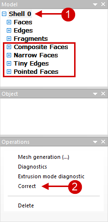
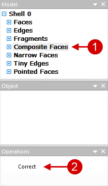
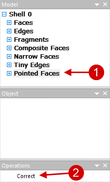
At the stage when the model is represented by a shell (Shell), it is always recommended to run diagnostic. To do this, you need to select the appropriate shell Shell 0, 1, 2... and in the window Operation execute the Diagnostic command. The Software can report unfavorable parts of the model which are recommended to be corrected for subsequent successful generation of the finite element mesh. The figure below shows a list of typical objects to fix: Fragments, Tiny Edges, Narrow Faces, Composite Faces, Pointed Faces
All unfavorable parts of the model can be auto corrected with one click. To do this, select Shell and in the window Operation click to Correct. After that, the software will fix all critical places on its own. During correction, new problematic edges and surfaces may appear, so it is recommended to select again Shell and in the window Operation click Diagnostic, and then - Correct:
With automatic correction, not all problematic edges and surfaces are shrunken and separated, but only the most critical ones, the change of which at the same time does not lead to a strong distortion of the initial geometry. In most cases, automatic correction is sufficient, and you can proceed to finite element mesh generation. See below for more details on the different types of problematic edges and surfaces. Fragments (fragments) are isolated part of the plain surface, which, if necessary, can be removed without violating the integrity of the model. Often the software designates some parts of the shaping plain surface of the tool as fragments, as in the figure above, such fragments should not be deleted. You can delete, for example, technological holes, recesses, inscriptions, if they are not important for simulation . This will lead to a simplification of the tool mesh and, consequently, to a reduction in simulation time . To delete an object, you must select the appropriate fragment in the list (this fragment will be highlighted in color on the wire fit by) and in the window Operation execute command Delete:
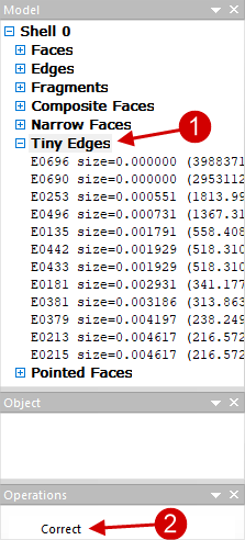
Tiny Edges (small edges) - very short curves on the model that can interfere with good mesh. If you click "+" opposite to the listTiny Edges, it will be opened. Here parameter size (size) shows the ratio of the length of the edge to some scale value determined by the dimensions of the body. In parentheses is its reverse value. It is recommended to origin select the entire list by clicking on Tiny Edges, and execute the command Correct in the Operationwindow. Automatic correction is optimal and sufficient at the first stage of the model correction. In this case, only edges are shinked with the parameter size which have less than 0.002. Edges that do not satisfy this condition are not auto removed. Because removing them can lead to geometry distortion:
If necessary, Tiny Edgesthat are not auto corrected , can be corrected manually. In this case, it is recommended to control changes in the geometry. Since the edges are very small, they are difficult to find without magnification. The simple way to find the edge selected in the list on the wire model is as follows: select in the list Tiny Edges any edge, click once with the mouse wheel in domain of the wire model, move the wire model as far as possible by rotation the mouse wheel, zoom in on the model by rotation the wheel in the opposite direction, while the object selected in the list will be in the center of the approach, it will be highlighted in color. In the Operation window click command Shrink. In some cases, the software may not shrink the selected edge for some reason, then you can try to execute the command Shrink with the Ctrl button clicked. Tiny Edges shrink to a point:
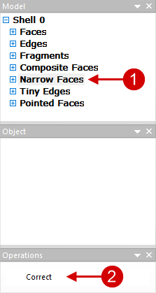
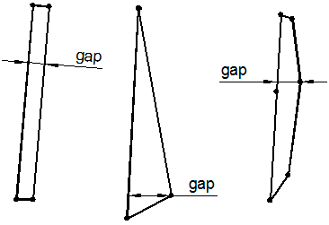
Narrow faces are narrow plain surfaces that can also adversely affect mesh generation. Like Tiny Edges, first you should try to fix it in auto mode. Listed Narrow faces parameter gap (gap) shows the ratio of the width of the elongated plain surface to some scale value determined by the dimensions of the body. The inverse value of this parameter is indicated in brackets (1/gap):
The figure below illustrates how the value gap is determined for different Narrow Faces:
If you need to shrink individual Narrow Faces, which are not auto-shrunk, this can be done manually. In this case, visual control of corrections is important. Similar to the manual fix of Tiny Edges select the desired plain surface in the Narrow faces list and find it in the wire model, then run the command Shrink. In some cases, the software may not shrink the selected edge for some reason, then you can try to execute the command Shrink with the Ctrl button clicked. As a result of executing the commands, the selected Narrow face shrinks into an edge:
Composite Faces are the plain surfaces with complex boundaries. It is recommended to correct all such plain surface before mesh generation . To do this, select the list Composite Faces and in the window Operation click Correct. All complex plain surface will be auto corrected and divided into several simpler ones:
Composite Faces can be corrected manual if necessary. To do this, select any object in the list Composite Faces, and this object will be highlighted in color on the wire model. In theOperationwindow run theSplit command. In thePlain surface division popup window, you should select two points by double-clicking on the edges of the plain surface along which the selectedComposite facewill be separated on two plain surfaces. Select the points and click OK:
Pointed faces (crescent plain surface) - it is recommended to correct similarly to Composite Faces:
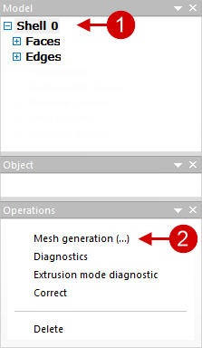
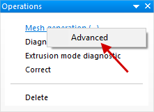
After making all the necessary corrections , a finite element mesh can be generated. To do this, you need to select the appropriate shell Shell and execute the command Mesh generation:
If necessary, you can execute the command Mesh generation by right mouse click, select Advanced and in the window that appears, adjust the density of the generated mesh by changing the parameters Adaptation And Element size coefficient . Maximum Adaptation value and minimum Element size coefficient value correspond to the maximum possible density of the generated mesh:
|


In some cases, after mesh generation, a remeshing error occurs and a list of Triangulation Errors appears that contains a plain surface that cannot be meshed. Most often this is due to the fact that the plain surface is very difficult to describe parametrically, and it needs to be simplified. One variants is to split a plain surface into multiple surfaces. To do this, you need to find a problematic place by selecting the corresponding plain surface in the list and finding it in the window for displaying geometric objects, and go back to the stage of work with the shell Shell:
In shell mode Shell you need to click on one of the edges of the problematic plain surface. Because one edge always refers to two plain surface, in the Object window in addition, you need to select the problematic face, after which it will be highlighted in red, and in the window Operation execute the Divide command:
Next, you need to specify by mouse click two points through which the line of separation of the plain surface will pass, and in the window plain surface division press OK:
The problematic plain surface will split into two plain surface, and you can try to generate the mesh again:
If this operation did not solve the problem, you can continue to separate the problematic surfaces in the Shell or try to fix the initial geometry in CAD- system. |


In some cases, when errors occur during the mesh generation, the problematic plain surface can conventionally be approximated by a flat plain surface, it can be made flat. You need to go back to the stage of work with the shell Shell, press the button Show spline plain surface on the toolbar, click on any edge next to the problem plain surface and in the Object window select the right Face. After that, the chosen Face will be painted over with spline lines, by which its curvature can be estimated. If the curvature is negligible, then this Face can be made flat by running the command Make it flat in the window Operation:
|

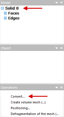
Geometry improvement is performed after generating a finite element mesh and converting solid geometric objects Solid to named objects, for example, in TOOL1, TOOL2, WPIECE etc.:
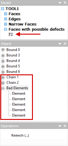
Originally you need to make sure that no Faces with possible defects or Narrow faces collections appear in the list of objects after the converting. If any of these collections appeared in the Model window, you need to examine its contents. The list contains plain surfaces on which problem areas were found. If you select any plain surface in this list, then in the window Object a list of all problem areas of this plain surface will be displayed:
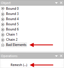
The most common mesh defects are bad elements (bad elements) and Chains (non-closed chain). Chains are not critical defects, and they should not be corrected. Bad elements should be corrected: their presence can lead to failure time simulation. Bad elements can be selected in the list and found on the finite element model. If you select one element on the bad elements list this element will be highlighted in color on the finite element model. After that in the Operation window, you need to execute the command Remesh. The figures below show a section of the mesh before and after remeshing :
You can select several or all at once bad elements and try to remesh them:
If for some reason it is not possible to remesh bad elements, you need to go back to the shell editing stage Shell and try to fix it manually. Tiny Edges And Narrow faces problem areas, if any. You can correct in the same way Chains. In addition to the commands Remesh for correction of Chains one more command is available - Round. After executing this commands , the software will offer to round the selected edge with the maximum allowable radius. It is recommended to use this function only when absolutely necessary:
|


In the process of mesh generation, as well as as a result of correcting mesh defects, local condensations can form. A more uniform mesh can be obtained by selecting the corresponding named object in the window Model and running the command Mesh defragmentation in the window Operation:
In some cases, as a result of defragmentation, there may again be bad elements, which need to be corrected. |

