Two basic examples of preparing geometry in QShape are below:
1. Run QShape and open the file C:\QForm UK\12.0.1\\geometry\ QShape \fork_tool1.stpcontaining the top die geometry . Due to symmetry, this example uses only a quarter die. A “wire” model will appear on screen, in the window Fit by object will appear Shell 0 (shell) and lists of second-level objects: Faces and Edges. If you click “+” opposite to any list, a complete list of objects will open. When selection an object in the list, the selected object is highlighted in color on the wire model. On the list Faces all the plain surface that make up the body are in the list Edges - all the ribs. In the window Model click on list Shell 0, and in the window Operations the following commands will appear: Mesh generation, Diagnostics and Delete:
2. Click Diagnostics. Now in the window Model three more lists appeared: Tiny Edges(small ribs), Narrow Faces(narrow plain surfaces), Pointed Faces(crescent plain surfaces) containing edges and plain surfaces that can cause problems when generating a finite element mesh. For beginning you can try fix them auto. In this case, the software will correct only some critical zones. To do this, select Shell 0 and in the window Operations click Correct:
Automatic correction is optimal and sufficient, even if no edge is optimized. If problems arise during subsequent mesh generation, you can always go back to the plain surface diagnostic stage and correct the selected small edges manually. To quickly find a problem zone on a geometric object, just select it in the list, click the mouse wheel on the geometric objects display window, and the center of rotation will be snapped to the center of the selected object. After this, by rotation the mouse wheel you can quickly find the problem area:
As a result of diagnostic, in some cases may also appear Composite faces (complex plain surface), which are also recommended to be corrected. This is described in more detail in the section Improvement of geometry and correction of defects. 3. In the window Model click on the list again Shell 0, then in the window Operations run the command Mesh generation, the model will begin to be meshed into finite elements. After that instead Shell 0 a list will appear Solid 0, and instead of the wire model, a finite element representation will appear:
4. In the window Model click on list Solid 0, then in the window Operations click Convert and select what the model should be converted to. In this case it is TOOL1:
After converting the list Solid 0 in the window Model will be renamed to TOOL1:
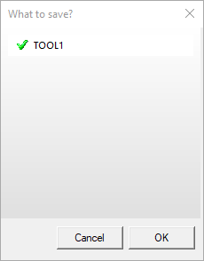
5. Save the geometry to SHL-file. To do this, in the main menu, click File, in the menu that opens – Save SHL. In the window that appears, you can select which object you want to save. By default, all file objects are enabled for saving. Click OK. Save as fork_tool1.shl:
6. By analogy, prepare the geometry for the lower tool (fork_tool2.stp) and workpieces (fork_wpiece.stp) and save them accordingly as fork_tool2.shl and fork_wpiece.shl. In QShape you can open several files at once. Their name will be displayed on the corresponding tabs:
For the convenience of viewing several files at once, you can hover over any bookmark with the cursor and right-click. Next select New Horizontal Tab Group or New Vertical Tab Group, depending on the order in which you want to see the window with geometry files. This is what the applications window looks like if select New Vertical Tab Group:
To go back to standard mode, hover over any bookmark with the cursor and right-click, select from the menu that appears Move to Next Tab Group or Move to Previous Tab Group, depending on the position of the window. 7. To create a file containing TOOL1, TOOL2 and WPIECE, it is necessary to make active any tab with any shl- file, for example, fork_tool2. Next in the menu Tools select item Paste SHL:
Paste one by one fork_tool1.shl and fork_wpiece.shl. After this, all three object will appear on screen, and in the list of models - WPIECE, TOOL1, TOOL2: 8. In order to move up tool a little, select in the window ModelTOOL1 and in the window Operations select Positioning/Change – Feed..., then move the upper tool 80 mm along the axes OZ:
Select the workpiece and, by analogy, move it 10 mm along the axes OZ. 9. Because In this example, only a quarter is considered; it is should be set two symmetry planes. To do this, first click on the first face for which should be set symmetry, and in the window Operations click Set symmetry plane. The edge will be color orange. Then you need to do the same for the second face:
10. Save a file with all objects, for example, like fork.shl for simulation in QForm. |


The examples in this section serve to introduce you to some basic capabilities QShape.
It is more convenient to load all objects at once from one assembly file prepared in a CAD system. If the geometry of objects is initially of sufficiently good quality, then you can import it into QFormdirectly from the STEP file.
Geometry prepared in QShape, for subsequent use in simulation it is necessary to save either in SHL- file (without a history of corrections and transformations), or in QShape- file (with history). Advantages SHL- the file lies in its small size. The advantages of a QShape file are the ability to open this file in QShape and go back to any stage of geometry preparation.