Let's consider an example of simulation a 3D task: hot bulk forging of a crank shaft fork for one action.
Initial data
Operation |
Operation type |
General forming |
Additional parameters |
With thermal process |
|
Problem type |
3D |
|
Geometry |
Load from file |
fork_3D.shl |
Workpiece parameters |
Material |
Steel C22 (1.0402) (Standard: File name) |
Temperature |
1200˚С |
|
Tool parameters |
Drive |
Tool 1 - Mechanical press 16 MN Tool 2 - Fixed drive +OZ |
Lubricant |
Tool 1, 2 - Graphite-water (Hot forging/Steels/Graphite + Water) |
|
Material |
Tool 1, 2 - H11 HRC51(Standard: File name) |
|
Temperature |
Tool 1, 2 - 200˚С |
|
Coupled tools simulation |
Not |
|
Heat transfer to workpiece |
Simple |
|
Stop conditions |
Distance |
4 mm between Tool 1 and Tool 2 |
Boundary conditions |
Environment |
Air 20˚C |
Blows |
Number of blows |
1 |
Cooling in air |
5 s |
|
Cooling on tool |
2 s |
|
Simulation parameters |
|
Default |
1.Click Create new process

2.In the tab Operation check Operation type - General forming, Problem type - 3D. Click Forward

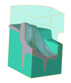
3.In the tab Geometry click Load from file and specify the path to the geometry file C:\QForm UK\12.0.1\geometry\fork\fork_3D.shl. The uploaded geometry will appear on screen. ClickForward

4.In the Workpiece parameters tab you need to set the material and workpiece temperature. Click next to Material[Select...]

In the database window that opens, select the material Steels\Carbon steels\C22 (1-0402) (Standard: File name) and double-click on it (or click the button Assign), after that the material will appear in the tabWorkpiece parameters

Set the workpiece temperature to 1200˚C. Click Forward

5.In the tab Tool parameters the drive type, temperature and lubricant must be select for each tool. To be noted that in this example Tool 1 - upper tool, and Tool 2 - bottom tool. Opposite Drive-Tool 1 click [Select...], and the equipment database window will be opened. Choose equipment Standard\Mechanical press\16MN and double click on it, after that the selected drive will appear opposite Drive-Tool 1

Tool 2 - fixed and it acts in the positive direction of the axesOZ. OppositeDrive-Tool 2 click [Select...], in the equipment database window, select Fixed drives\+OZ and double click on it, the selected drive will appear opposite Drive-Tool 2

Opposite Lubricant click [Select...] and double click to set the lubricant Hot forging/Steels/Graphite+Water. Lubricant will appear immediately for all tools.
Opposite Material click [Select...] and double click to set the material H11 HRC51 (Standard: File name). The Material will appear immediately for all tools.
OppositeTemperature set the tool temperature to200 °C. Click Forward.
6.In the Stop conditions tab you should set final distance between the tools. In the window Add conditionclick Distance. After that, specify the value of the final distance (4 mm) in the window Stopconditionssimulation. Tools between which it is set will be auto selected, because simulation are total two of them. Click Forward

7.In the Boundary conditions tab all remains unchanged. Click Forward

8.In the tab Blows set the cooling in air to 5 seconds and in the tool to 2 seconds. Click Forward

9.In the Simulation parameters tab all remains unchanged. Click OK.
10.Click Simulation![]() , and the program will prompt save the project. Enter the project a name and click OK. The simulation will start
, and the program will prompt save the project. Enter the project a name and click OK. The simulation will start

11.After the solver finished, activate the first record of the simulation and in the tab Tracking points and line create a array of lines

12.Specify three point approximately along the axis of the workpiece. Click Create point and double-click create three point in domain the workpiece axis area, then click Execute tracking for the operation, and the post-processor tracking of the created lines and points will begin

13.In the tab Subroutines add a standard subroutine Surface flow analysis, then click Execute subroutines, the post-processor simulation of the added subroutines will start

See also: