The Geometry for simulation should be prepared in the CAD systems as 3-D solids or 2-D contours, that can be converted to 3-D solids in the QShape geometry editor.
Axes of rotation must be specified for all tools involved in the rolling process. The axes my be specified in the QShape editor or directly when preparing the initial data in the tab Geometry. It is not necessary to specify an axis for the workpiece, because the workpiece rotates as a result of contact with the main roll and mandrel. The workpiece geometry can also be transferred from previous forging operations with all calculated fields.
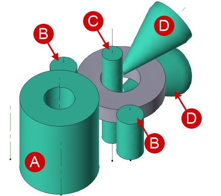
All main tools needed for simulation ring rolling is shown in the figure below.
|
A - main roll; B - guide rolls; C - mandrel; D - axial rolls. |
|
Important |
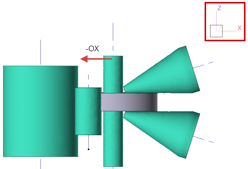
All tools and the workpiece must be positioned so that the horizontal movement of the mandrel is strictly performed against the axis OX of the global coordinate system, as shown in the figure below. |
|
The axis of the main roll must pass through the coordinate origin.
|
Positioning of the objects in the global coordinate system |
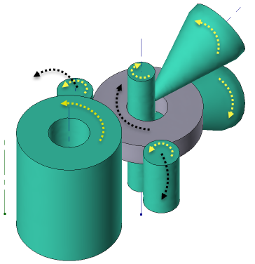
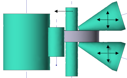
Motion directions of all tools is shown in the figure below
|
|
|
Rotation of tools and workpiece during the process |
|
Translatory motion of mandrel and axial rolls |
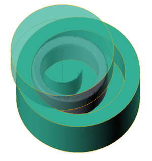
It is possible to simulate other ring rolling schemes in the QForm UK, e.g. closed rolling.
|
Closed ring rolling |