This example considers the preparation of a hexahedral finite element mesh for a tubular workpiece with a diameter of 30 mm, a thickness of 2 mm, and a length of 150 mm.
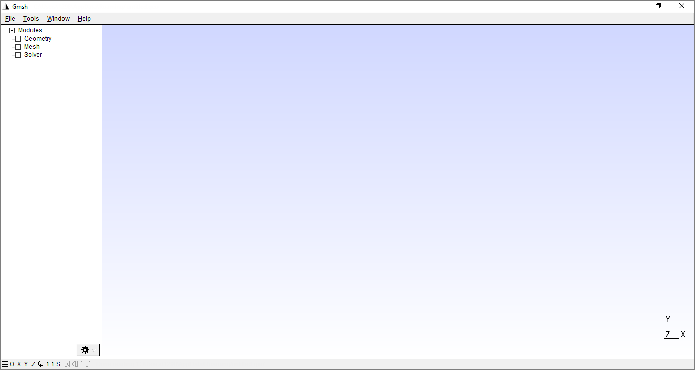
1.You need to open the Gmsh software.
|
Information |
To work with the new geometry, you need to start work with a new file. To do this, you should click File > New. |
|
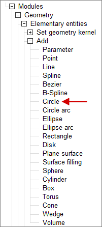
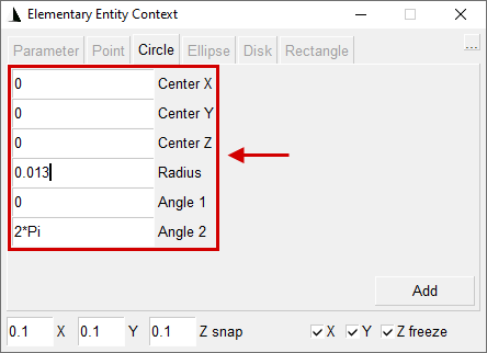
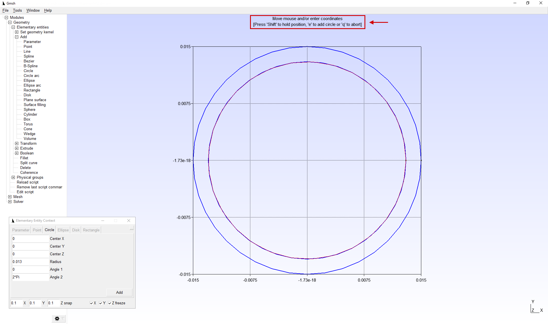
2.First of all, you need to create a circle with a radius of 0.015 m. To do this, use the feature Geometry > Elementary entities > Add > Circle. Then, in the window that opens, you must enter the coordinates of the center, the circular radius and click the button Add.
|
Information |
In theGmsh software the SI measurements system is used, i.e. distance is indicated in meters. |
|
|
|

3.Repeat step 2 and create a circle with a radius of 0.013 m.
4.After the circles have appeared in the domain, you must click "Q » to exit create mode Circle.
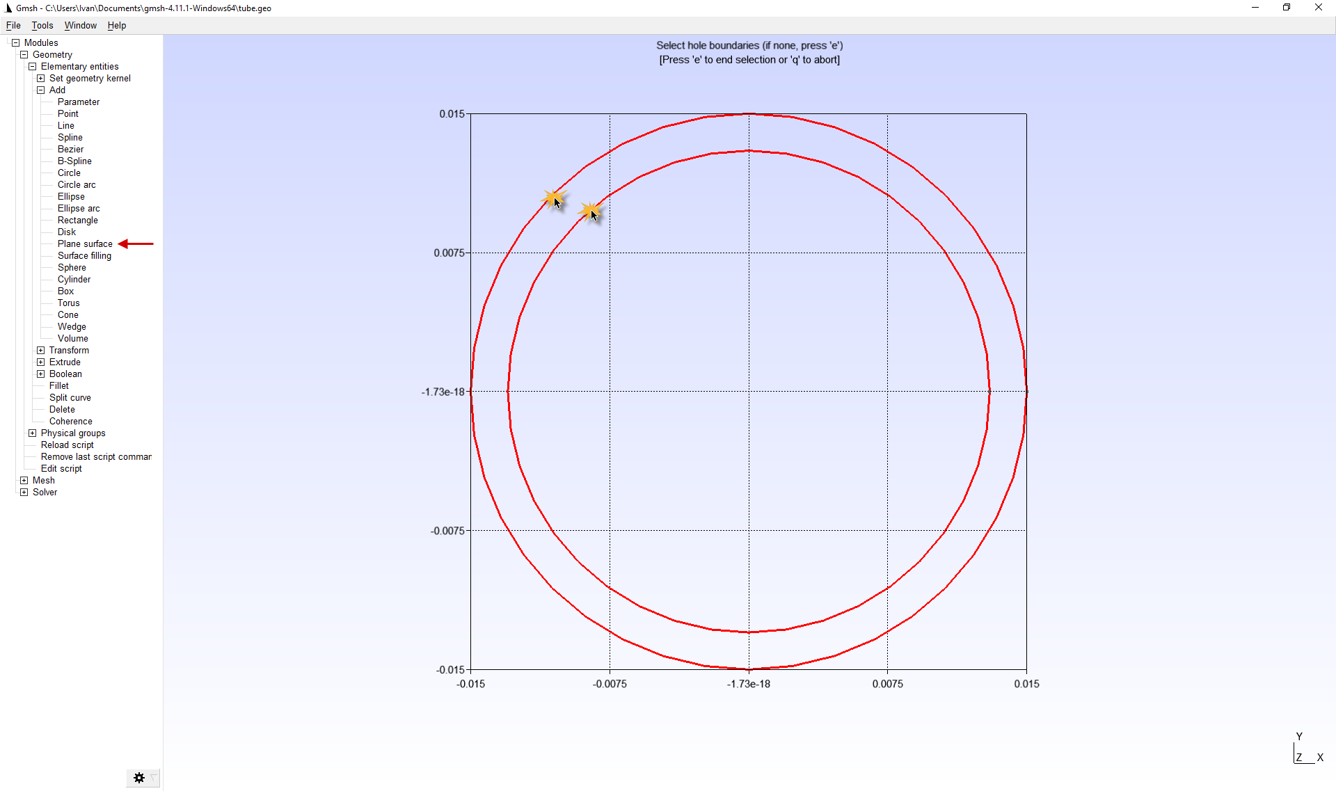
5.Let's use the featureGeometry > Elementary entities > Add > Plane surface to create a plain surface from pre-prepared geometry. After activating the mode Plane surface you need to select the inner and outer boundaries of the contour and click "E ", and then "Q ".
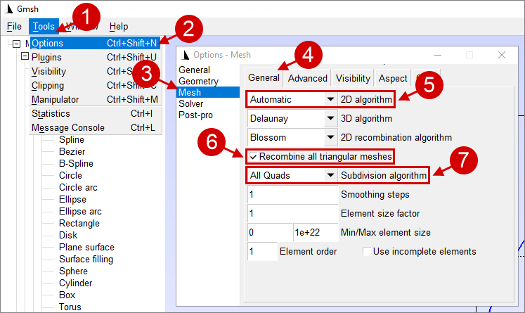
6.In the applications parameters Tools > Options > Mesh > General need to switch 2D algorithm on Automatic, activate Recombine all triangular meshes. Also, for the subdivision algorithm parameter select All Quads. After completing all the manipulations, the options window can be closed.
|
Information |
When using the different combinations of options and meshing algorithms, it is possible to obtain the desired calculation mesh. |
|
|
Important |
Options are applied only to the currentGmsh software window. Every time you start theGmsh software all features are reset to default values. |
|
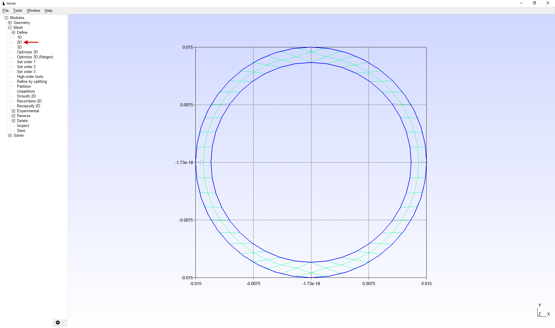
7.To create a 2D finite element mesh, use the Mesh > 2D feature.
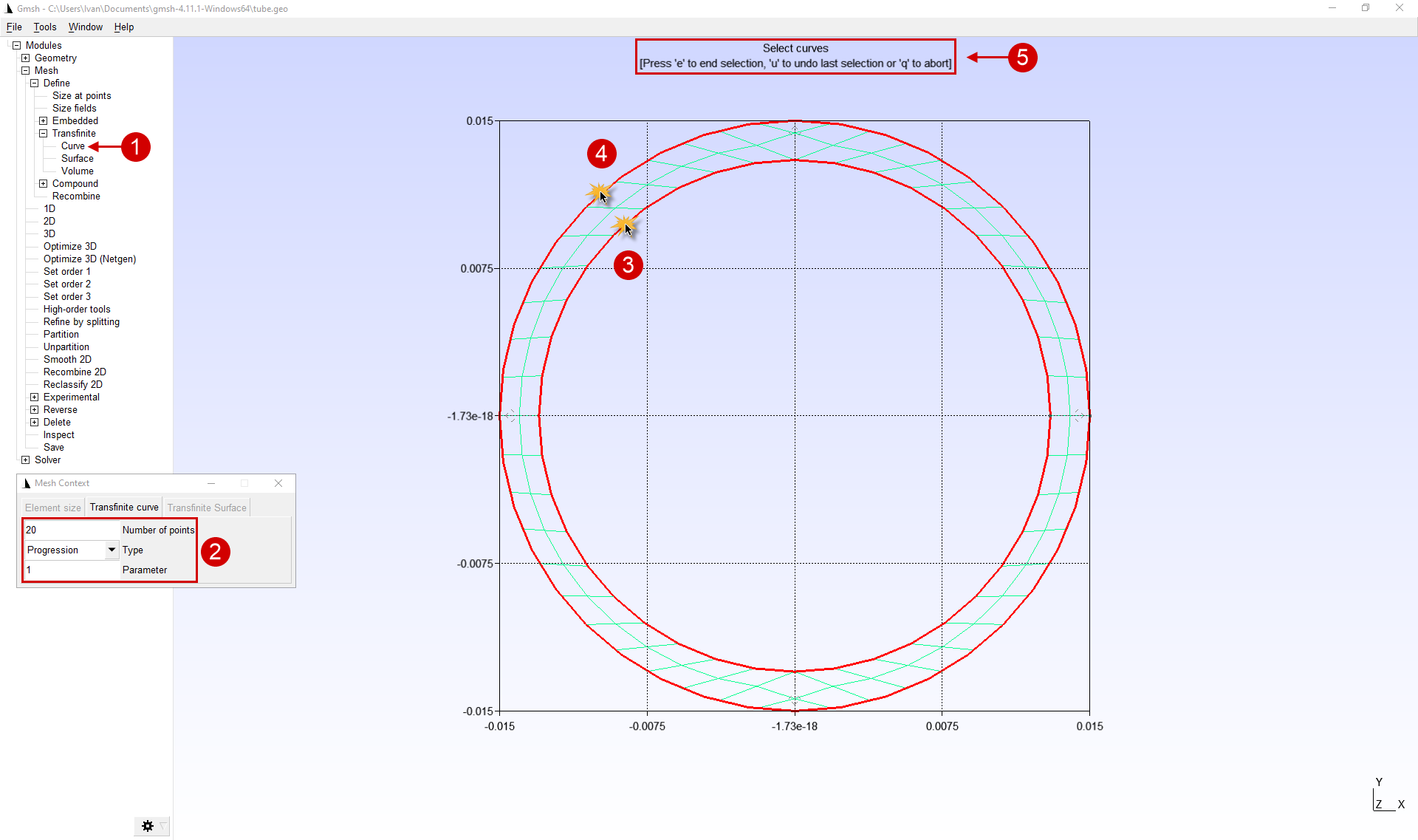
8.To improve the quality of the mesh , increase the amount of nodes along the circle using the feature Mesh > Define > Transfinite > Curve. After setting the parameters in the window that appears and selecting 2 circles, click "E ", and then "Q ".
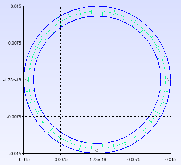
9.For remeshing, you must sequentially activate the feature Mesh > 1D And Mesh > 2D.
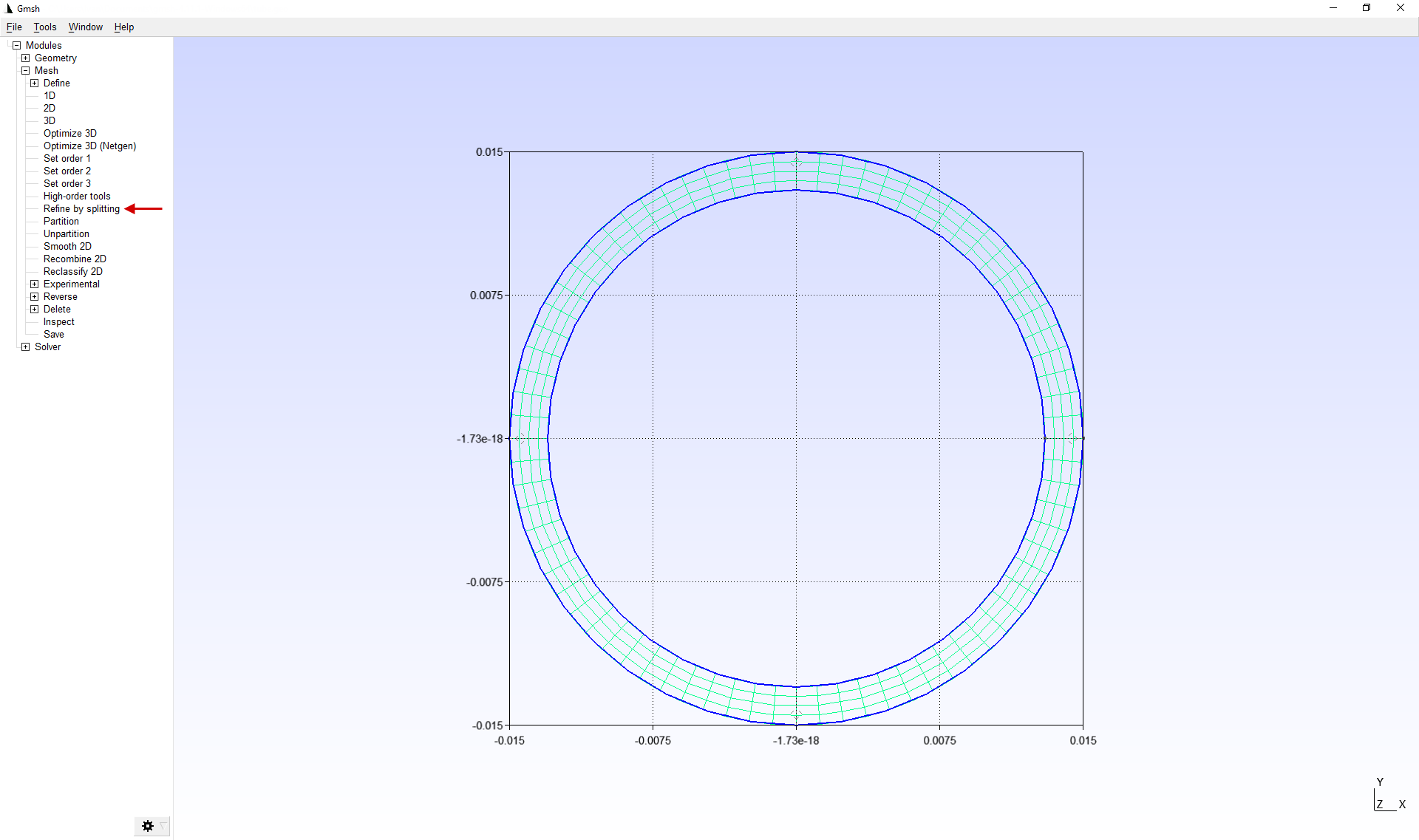
10.For additional mesh refinement, you can use the feature Refine by splitting. This feature divides each element by 4. In this case, this feature is needed to refine the mesh in the radial direction.
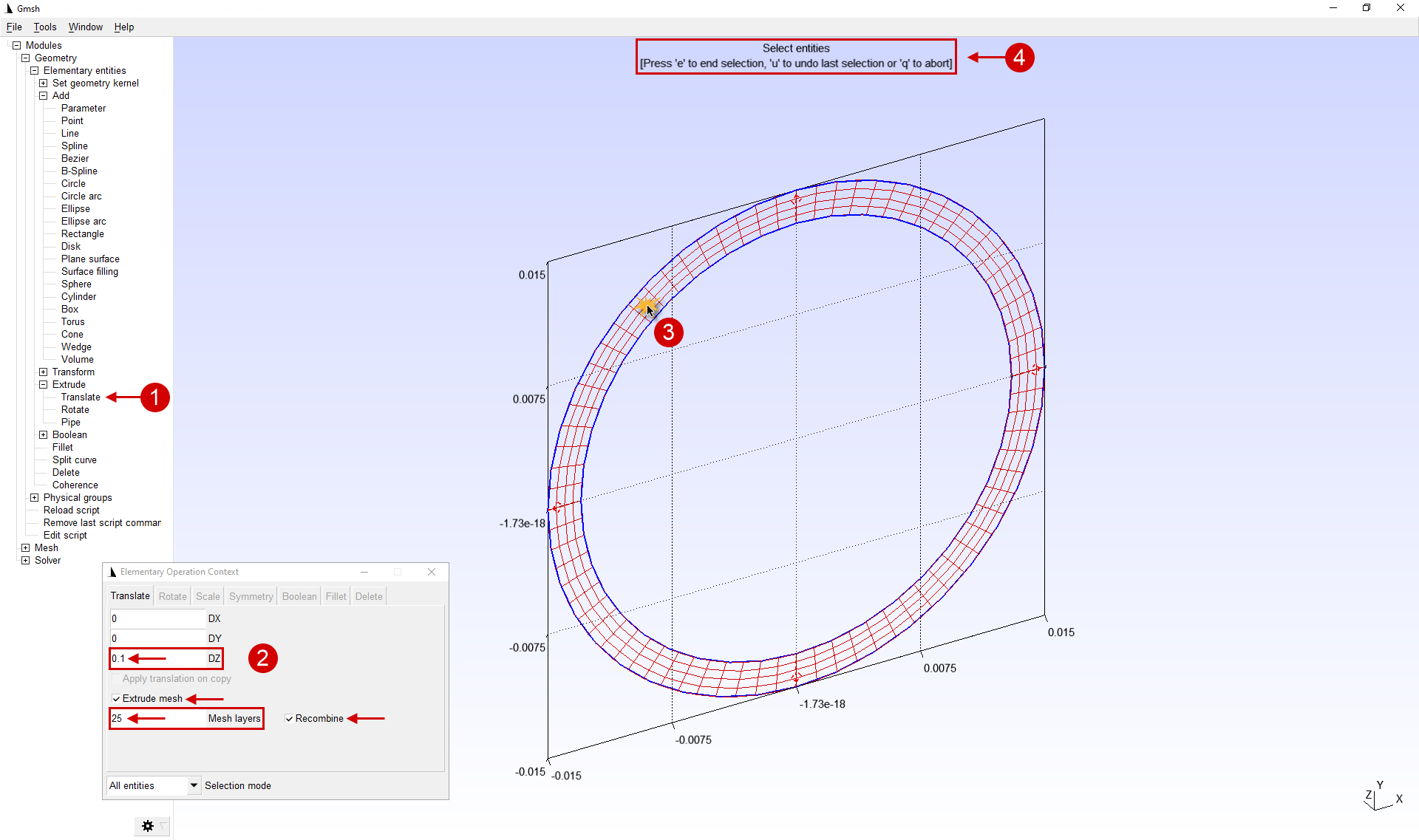
11.Then we translate the flat mesh into a three-dimensional one. Let's use the featureGeometry > Elementary entities > Extrude > Translate. We conditionally divide the pipe into 2 part. The first part is 100 mm length and 25 elements in length. The second part is 50 mm and 50 elements in length. For the first part in the parameters, you must specify the length along the axis Z (0, 1 m), the elements count along the length Mesh layers (25 items), and activate the feature Extrude mesh And Recombine. Then we select a 2D mesh for translation (mesh only, no contour). To do this, just left-click on the previously created 2D mesh, which will be highlighted. in color. After all these manipulations are carried out, you must click the "E ".
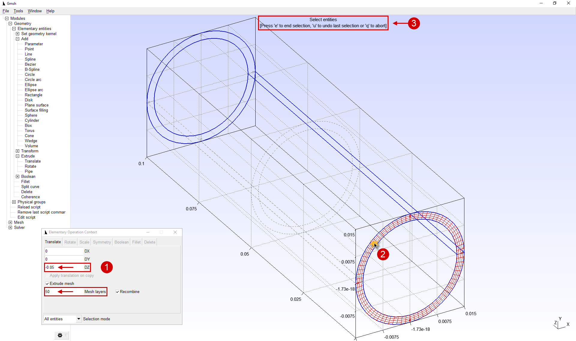
12.For the second part in the parameters , you must specify the length along the axis Z (-o.05 m, negative value for translation in the opposite direction), the elements count along the length Mesh layers (50 elements) and activate feature Extrude mesh And Recombine. Then we select a 2D mesh for translation (mesh only, no contour). To do this, just click the left mouse button on the previously created 2D mesh, which will be highlighted. in color. After all these manipulations are carried out, you must click the "E ", and then "Q » to exit the featuretranslate.
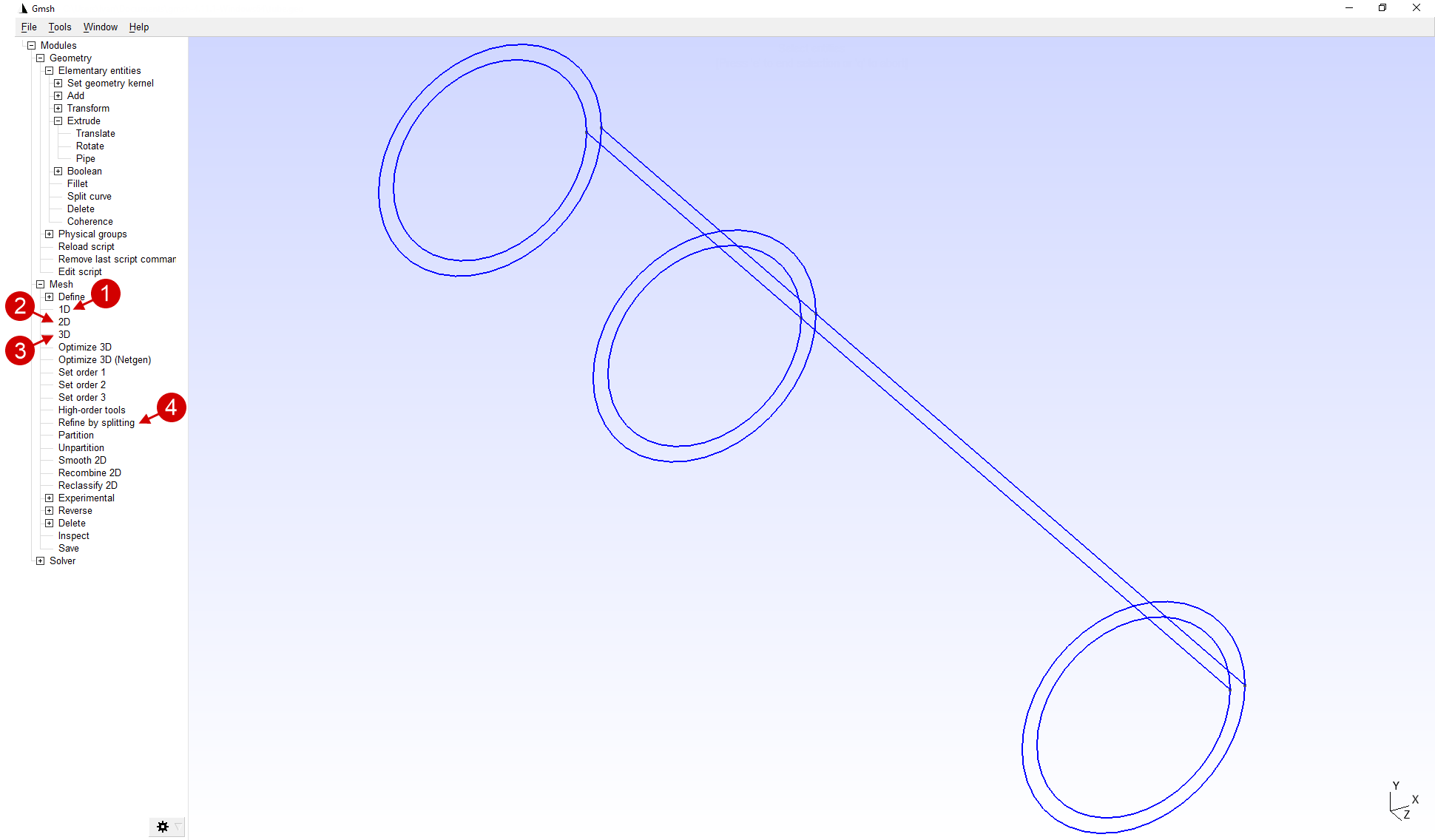
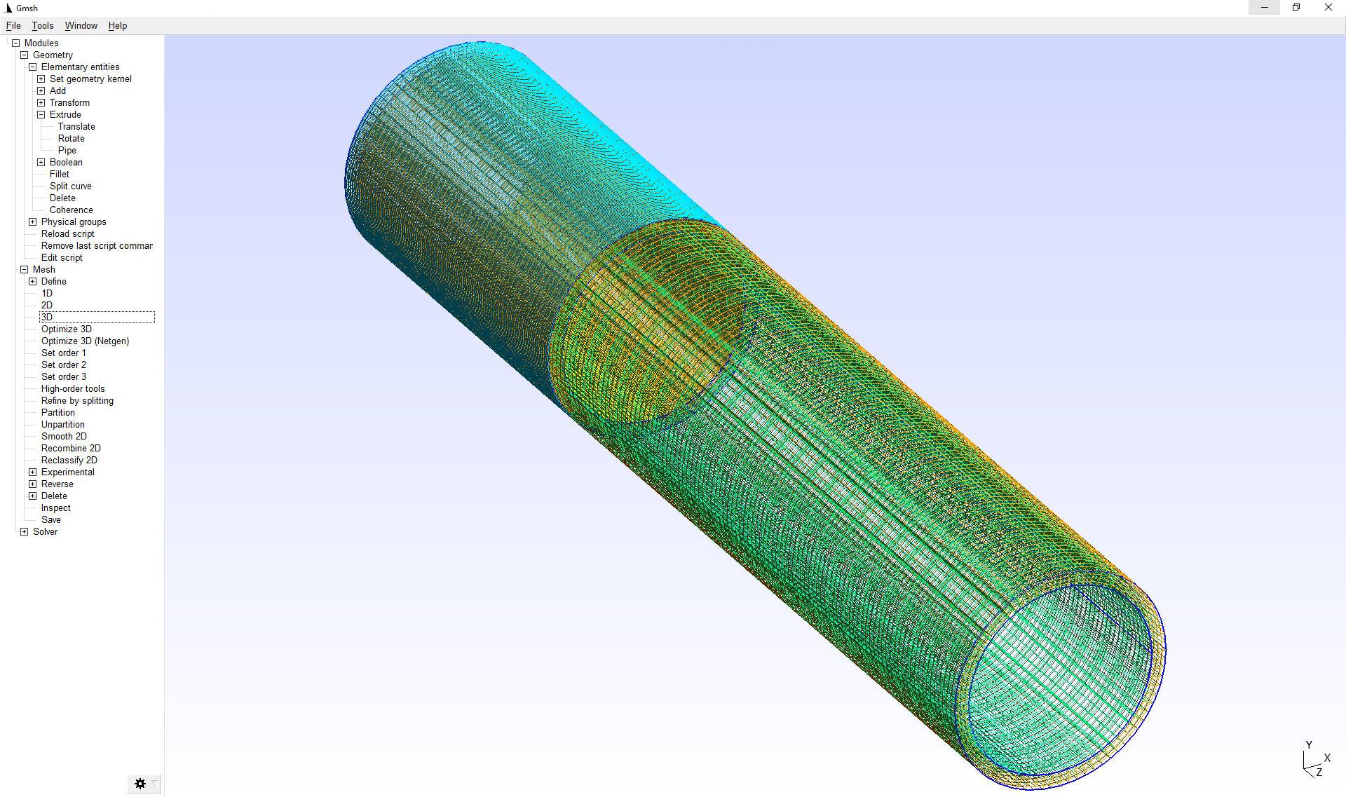
13.Next, you need to sequentially activate the feature Mesh > 1D, Mesh > 2D, Refine by splitting And Mesh > 3D to create a volumetric finite element mesh.
After executing the sequence of commands from the paragraph, the calculation mesh will consist of both 2D and 3D elements.
|
Important |
QForm supports the import of only computational meshes consisting of elements of the same dimension. If the calculation mesh consists of elements of different dimensions, for example, 2D and 3D elements, then when importing into QForm an error occurs. |
|
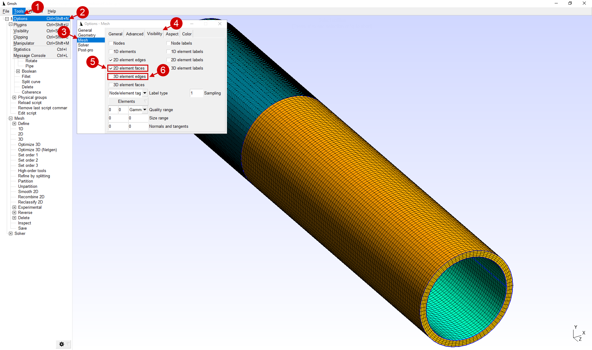
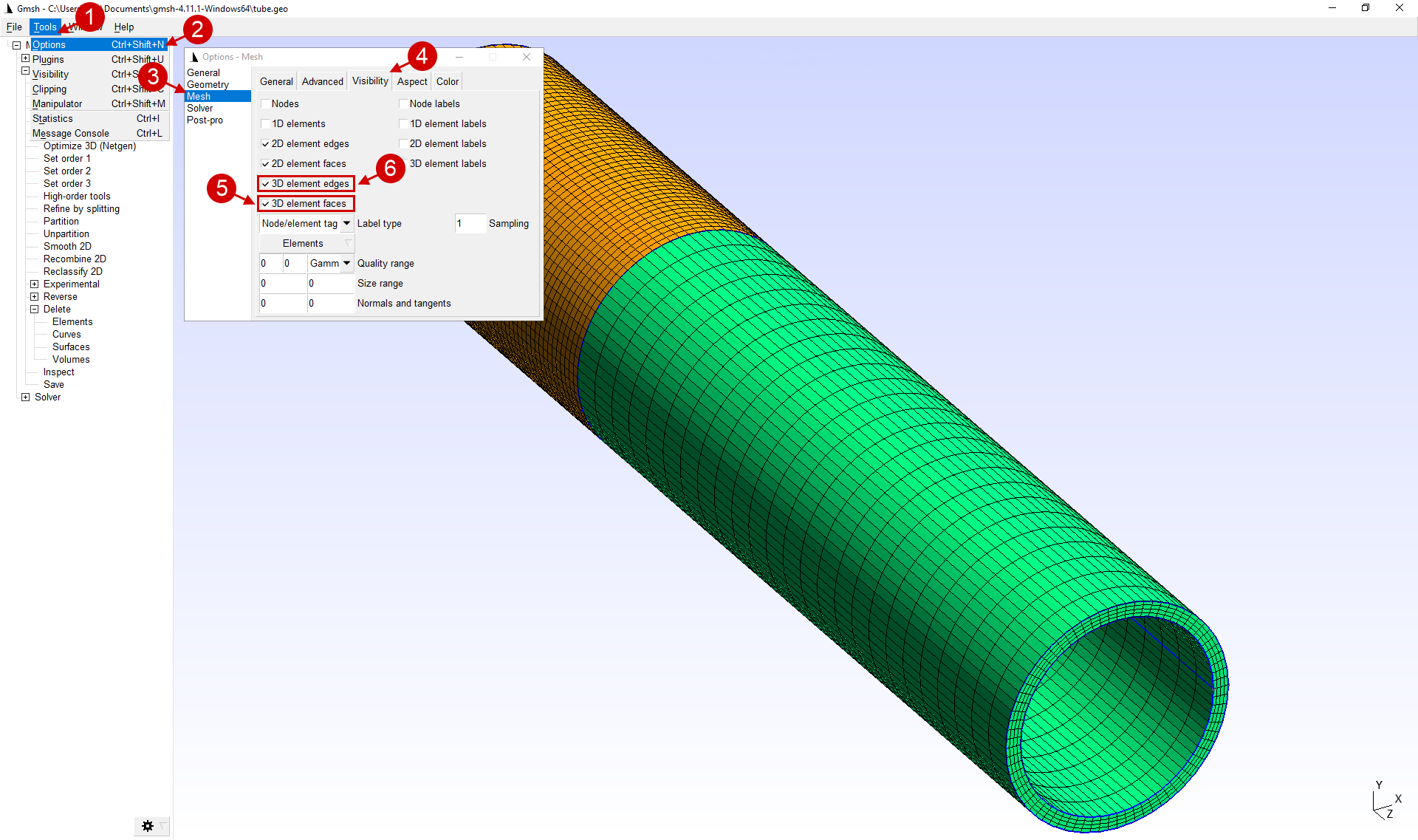
14.2D elements must be delete before export . In the applications parameters Tools > Options > Mesh > Visibility must enable display 2D element faces and disable display 3D element edges. After completing all the manipulations, the options window can be closed.
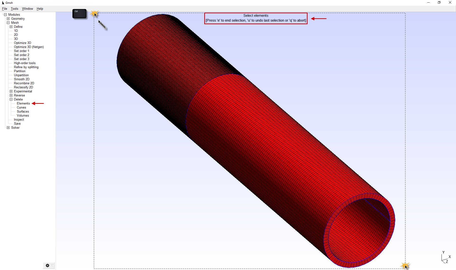
15.To delete 2D elements, use the feature Mesh > Delete > Elements. Next, you need to select all elements with the help of the selection domain . To start selection, hold down Ctrl click the left mouse button at the origin of the selection. To end the selection, click the left mouse button at the end of the selection. After all these manipulations are carried out, you must click the "E ", and then "Q » to exit the featureDelete.
16.To make sure that the calculation mesh is built correctly and consists of 3D elements, it is necessary in the software parameters Tools > Options > Mesh > Visibility to enable the display 3D element faces And 3D element edges. After completing all the manipulations, the options window can be closed.
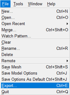
17.The Mesh is ready for export. For correct importing of the generated mesh in QForm it must be exported in the *.unv format. To do this, in the File tab use the Export feature.
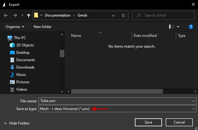
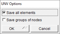
18.In the window that opens, set the file name (be sure to include the extension in the file name *.unv) and choose file Type > Mesh-I-deas Universal. Next click Save. In the opened window UNV Options choose Save all elements and press OK.
|
|
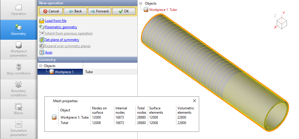
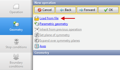
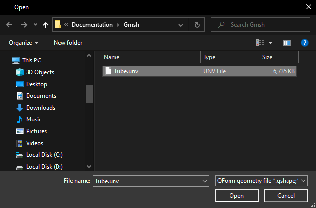
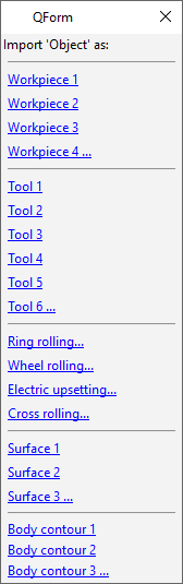
19.The Mesh is ready to be imported into QForm UK. To do this, in the Geometry tab you need to click Load from file and select the exported file. Next, in the window that appears, select the name of the object, for example, Workpiece 1.
|
|
|
20.When loading a mesh it is possible to change the units of measurements. This can be done by selecting the Units of measure at importfeature in the journal or by selecting the loaded mesh and clicking on Measurements units in the Properties window.
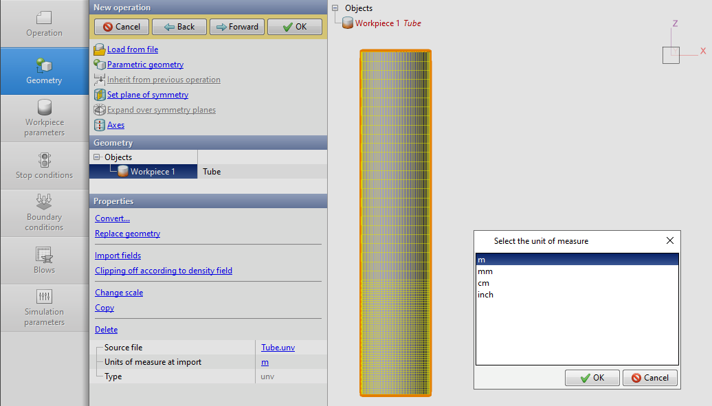
21.The loaded mesh is ready for simulation.