QForm UK has a built-in finite element mesh generator that creates quadrilateral meshes. This tool allows dividing a geometric object, represented as a flat bounded surface, into a mesh according to user-defined parameters. The resulting mesh can be converted into a hexahedral finite element mesh and used as a workpiece for simulations, including sheet bulk forming operations.
To create a two-dimensional mesh of quadrilateral elements for the workpiece and subsequently generate a volumetric hexahedral mesh based on it, follow these steps:
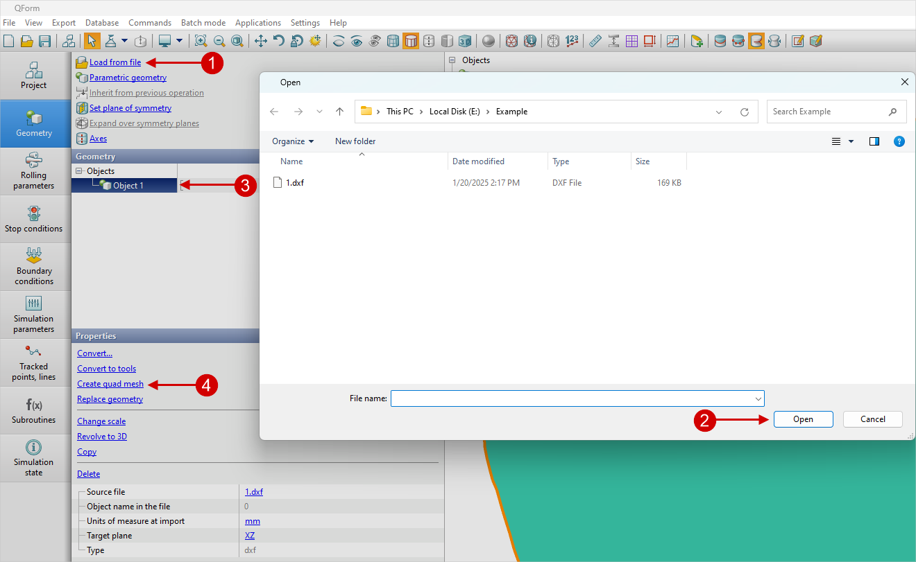
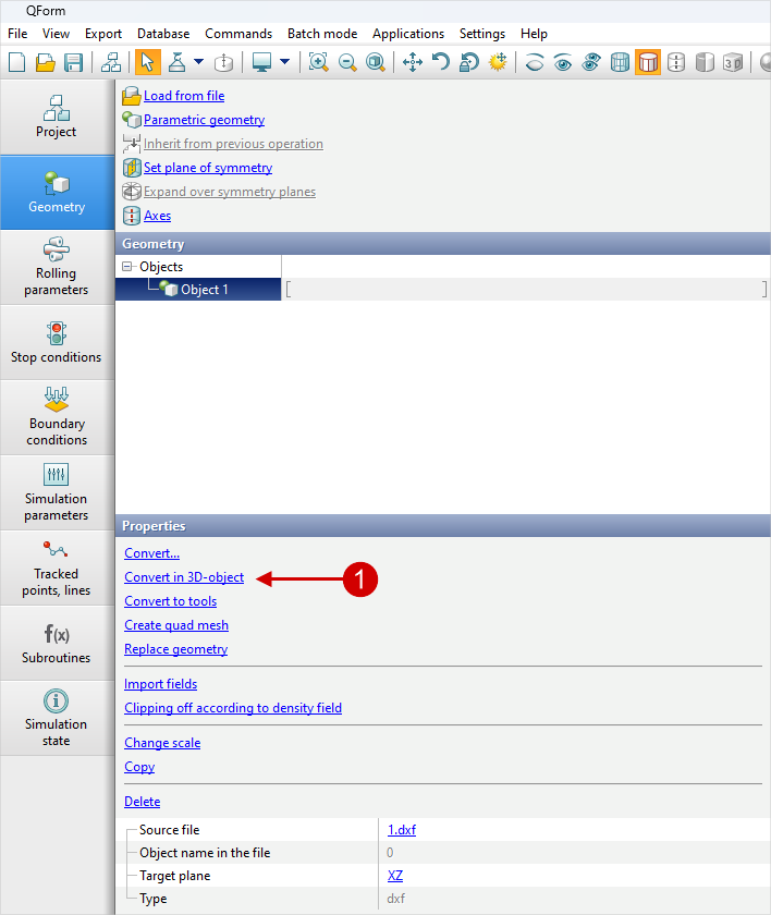
1.Load the prepared workpiece geometry as a surface contour saved in .dxf format by clicking Load from file (1) in the Geometry tab and selecting the required file. Then, in the Properties section, click Create quad mesh (3) .
|
Information |
1. The generator can only be used to create finite element meshes for flat workpieces. 2. When creating a quadrilateral mesh, imported geometry should represent a surface without thickness rather than a solid body. |
|
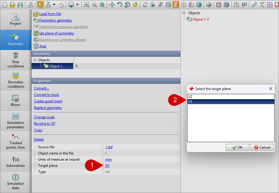
After loading the geometry as a surface contour saved in the dxf format, it can be placed in two planes: XY and XZ. In the Properties, click the Target Plane (1), then select the XZ or XY plane (2).
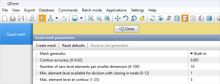
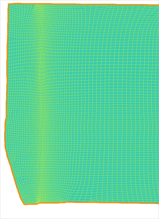
2.In the Quad mesh panel that appears, specify the parameters for the mesh to be created, then click Create mesh . If you are satisfied with the created mesh, click Close . If not, adjust the previously entered parameter values and regenerate the mesh by clicking Create mesh. After the initial mesh is created, an additional section, Creation mode appears in the parameters, allowing you to choose one of two available options: Replace current mesh or Create a new object . If the option Replace current mesh is selected, clicking Create mesh will replace the existing mesh with a new one. If the Create a new object option is selected, clicking Create mesh will create a copy of the original object and generate a mesh for it. In this case, the previously created mesh for the original object will remain unchanged. The Quad mesh panel also provides two buttons: Reset defaults and Reset to last generated . Clicking the first button will reset the mesh parameters to their default values, while clicking the second button will restore the values used during the most recent mesh generation.
| Quad mesh parameters (build-in generator) |
•Contour accuracy When creating a quadrilateral mesh, the generator uses the object's contour represented by a polyline consisting of segments included in the imported contour geometry, as well as segments approximating its curved sections. At the final stage of mesh creation, its outer nodes are pulled from the simplified polyline contour onto the original imported object contour. The size and number of segments used to approximate the curved sections of the contour are determined by its curvature and length, respectively. The segment size, in turn, affects the size of the mesh elements used in that part of the contour. To increase the length of segments and, consequently, the size of the mesh elements used by the generator, the Douglas–Peucker algorithm is applied. This algorithm replaces the original polyline that approximates a curved section of the contour with a simpler polyline composed of fewer, longer segments, ensuring that the deviation from the original polyline does not exceed a specified value. The allowable deviation is determined by the Contour accuracy parameter. The smaller the value of this parameter, the more closely the simplified polyline matches the original contour, resulting in smaller segments being used. •Number of zero level elements per smaller dimension At the initial stage of mesh generation, a regular mesh is created for the rectangle enclosing the workpiece. It consists of square elements, conventionally referred to as zero-level elements. The number of elements used along the shorter side of the enclosing rectangle is specified by the parameter Number of zero level elements per smaller dimension . •Max. element level at contour Subsequently, the regular mesh corresponding to the enclosing rectangle is adjusted to reflect the actual boundaries of the object defined by its contour. In this case, accurately representing the contour elements may require repeated subdivision of the zero level elements until elements of the desired size are obtained. If a zero level element is subdivided into four smaller elements, these newly formed elements are conventionally referred to as first level elements. If a first level element is subsequently subdivided into four elements, the resulting elements are conventionally referred to as second level elements. Etc. To limit the maximum number of subdivisions for zero-level elements, the parameter Max. element level by contour is used. •Min element level available for division with closing in node When subdividing an element, if an adjacent element sharing an edge has not been subdivided as well, an inconsistent node may be formed. The creation of quadrilateral meshes with inconsistent nodes is disabled. Therefore, if such a situation occurs, one of two approaches is currently applied. According to the first approach, if inconsistent nodes arise, the neighboring elements are subdivided accordingly. If this again results in inconsistent nodes on the edges of neighboring elements, those elements will also be subdivided. This process continues until all inconsistent nodes on element edges are eliminated. In the second approach, when an element is subdivided along the edge of an adjacent element that cannot be subdivided, a new element is created without any inconsistent nodes. The edges of this element are closed at the nodes of adjacent elements. Using the Min element level available for division with closing in node the level of an element available for division with a closure at the node is set to the elements starting from which level the second approach is available for division.
|

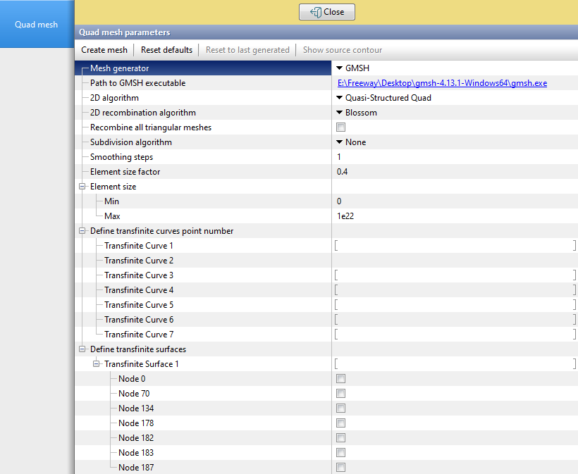
| Quad mesh parameters (GMSH) |
•Path to GMSH executable
To use GMSH as a generator, the GMSH (https://gmsh.info/) must be installed, and the path to its executable file (...\gmsh.exe) must be specified here. •2D algorithm This parameter specifies the strategy for constructing the two-dimensional quad mesh: •Frontal-Delaunay for Quads - provides a good balance of quality and controlled frontal recombination, which is useful for arbitrary domains with complex, non-symmetric geometry. •Quasi-Structured Quad - suitable when a more structured mesh with explicit line directions is required, for example in domains with clear symmetry or a computable layering direction. •2D recombination algorithm This parameter defines the method GMSH will use to recombine pairs of triangular elements into quadrilaterals after the two-dimensional mesh has already been generated. Recombining triangles into quadrilaterals makes it possible to obtain a smoother and more structured mesh of quad elements. The following variants of recombination algorithms are used in QForm UK: •Simple - a basic recombination method. Adjacent triangles are recombined into quadrilaterals, but the resulting elements are not guaranteed to have an optimal shape. •Blossom - based on the Blossom-Quad algorithm, it determines the optimal way to pair triangles, ensuring the highest possible quality of the resulting quadrilaterals. •Simple Full-Quad - an extended version of the Simple method. Attempts to recombine all triangles into quadrilaterals so that no triangles remain in the mesh. •Blossom Full-Quad is a combined Blossom-Quad approach with a full recommendation of a triangle grid. This results in a fully quadrilateral mesh with maximum consistency. •Recombine all triangular meshes Enabling this parameter after GMSH mesh generation will automatically run the selected 2D recombination algorithm on the entire mesh. If the parameter is disabled, the recombination algorithm is applied only to explicitly defined transfinite surfaces. •Subdivision algorithm This parameter defines whether an additional subdivision of each mesh element will be performed after the initial generation. •None - no additional subdivision is performed; •All Quads - forces GMSH to further subdivide each element (triangle or previously generated quadrilateral) into four smaller quadrilaterals, increasing mesh density while preserving the quadrilateral structure. •Smoothing steps Defines the number of mesh post-processing iterations during which element vertices are relocated according to the selected smoothing algorithm. Each smoothing step adjusts the element shapes to improve angle quality and reduce sharp or highly elongated cells, but it may slightly modify the original mesh geometry and increase the generation time. In most cases, 1–3 smoothing steps are sufficient. Using a value higher than 5 is not recommended. •Element size factor This parameter specifies a global multiplier that is applied to all computed characteristic element lengths. During mesh generation, GMSH first determines the element sizes based on geometry and curvature, and then multiplies them by this coefficient. Thus, when the Element size factor is set greater than 1, all elements become proportionally larger, while values less than 1 reduce the element size (resulting in a denser mesh). •Element size (min, max) These parameters define strict limits on the side lengths of the generated elements across the entire geometry. This means that during mesh generation, elements cannot be smaller than Element size min or larger than Element size max. Decreasing the max value increases mesh density in unconstrained regions, where otherwise excessively large triangles or quadrilaterals might be generated. Increasing the min value prevents excessive refinement in high-curvature regions, which can speed up generation but may reduce approximation accuracy. •Define transfinite curves point number Specifies the exact number of nodes (vertices) along a defined Transfinite curve. When this meshing method is used, GMSH uniformly distributes the specified number of points along the curve and then generates elements between them. Always ensure that the number of points is consistent across all curves forming the boundary of a Transfinite surface in order to obtain an ordered, structured mesh (for example, for a rectangle: use the same N on two opposite curves, and a separate M on the others). •Define transfinite surfaces This parameter enables the transfinite meshing algorithm on the selected surfaces. Once the number of points has been defined for all boundary curves of the surface using Define transfinite curves point number, GMSH uniformly generates a mesh of elements on each specified surface. This makes it possible to obtain a well-structured and consistent mesh. |
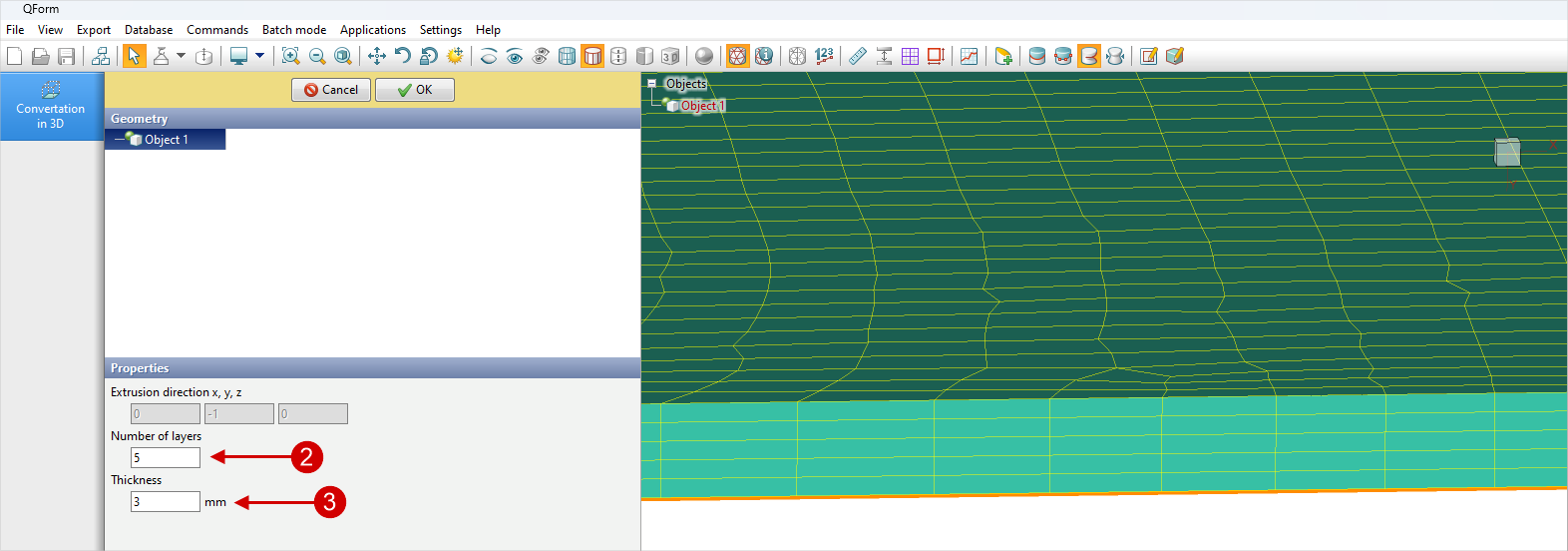
3.To convert the created quadrilateral mesh into a hexahedral mesh, go to the Geometry tab for the object, select the Convert to 3D option (1) in the Properties section , and then set the parameters for the generated volumetric mesh in the Convert in 3D-object panel that appears. The volumetric mesh is created by extrusion of the elements from the 2D mesh used, based on the Thickness (2) value specified as a parameter, in the direction normal to the surface of the workpiece. This direction is determined automatically and, for a flat workpiece, coincides with the thickness. The elements used along the thickness of the volumetric mesh are identical, and their quantity is determined by the value of the Number of layers (3) parameter.
|
|
The selection of the Convert in 3D-object option |
The selection of conversion parameters and the displayed result |
4.To use the prepared hexahedral mesh as a workpiece, the corresponding object must be converted into one of the named workpieces. To do this, go to the Geometry tab for the object, in the Properties section, click Convert... , and select the desired model from the list that appears.